

Heat transfer system and method for turbine engine using heat pipes
a technology of heat transfer system and turbine engine, which is applied in the direction of machines/engines, efficient propulsion technologies, stators, etc., can solve the problems of pressure loss, significant fuel burn penalty, cost and weight penalties associated with this configuration,
Patent Information
- Authority / Receiving Office
- US · United States
- Patent Type
- Patents(United States)
- Current Assignee / Owner
- Publication Date
- 2011-03-08
Smart Images
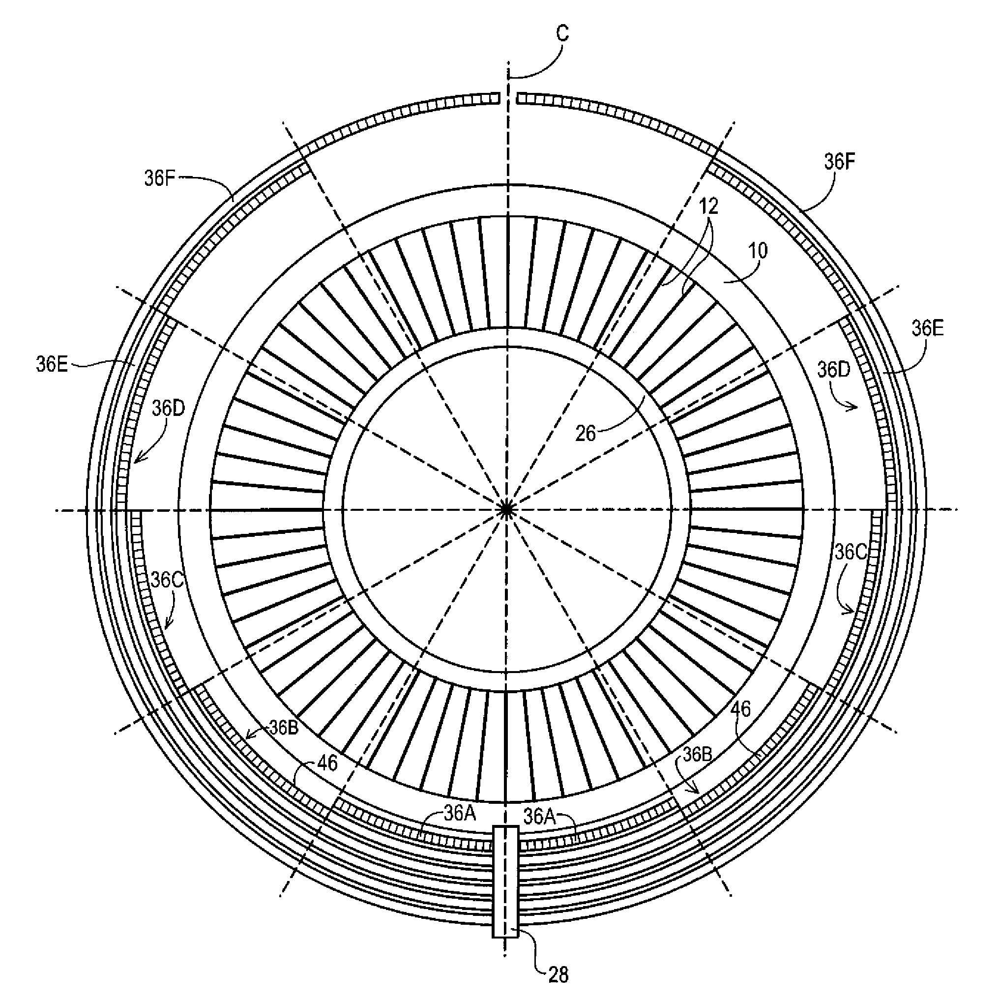
Figure 1 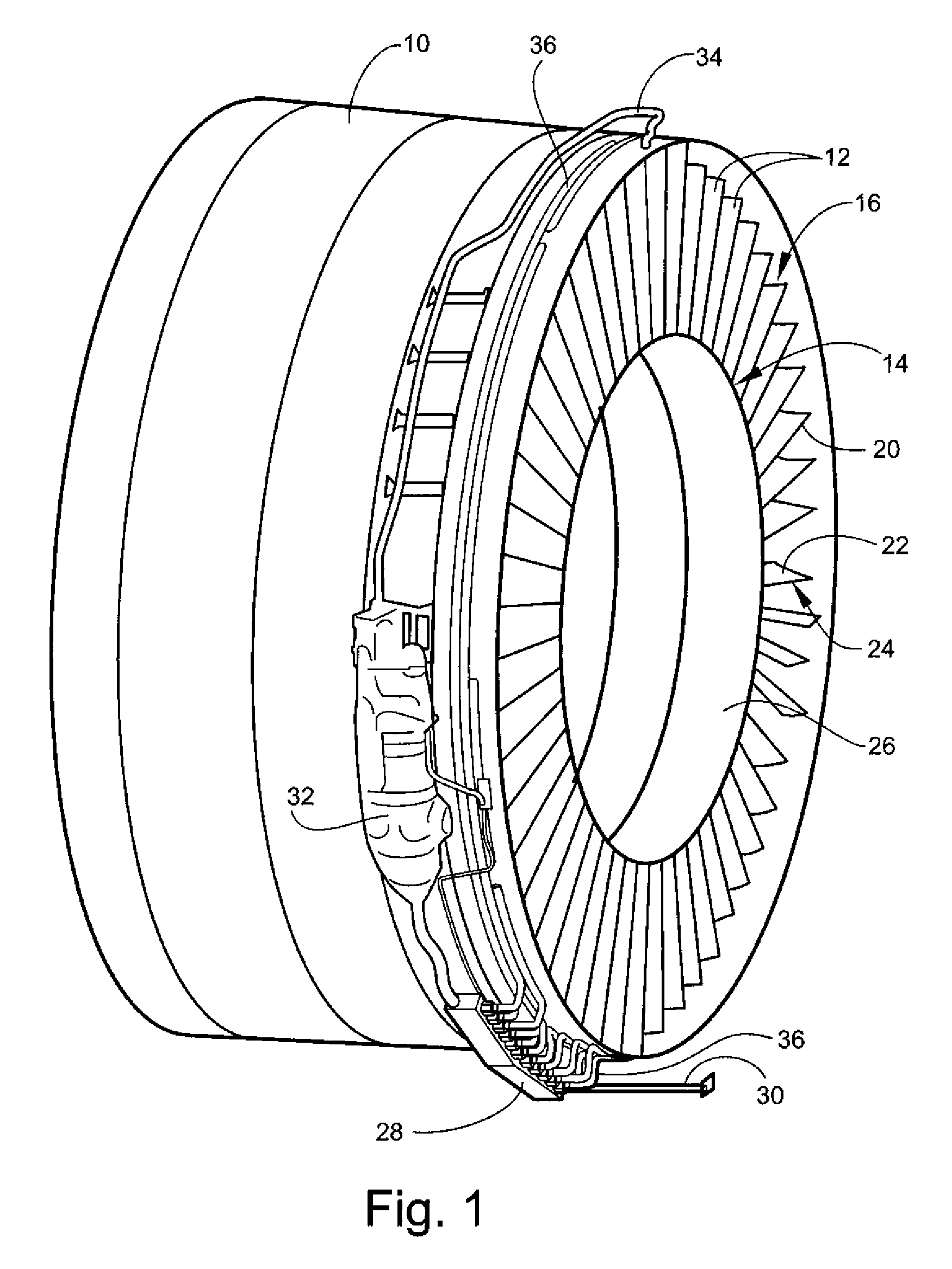
Figure 2 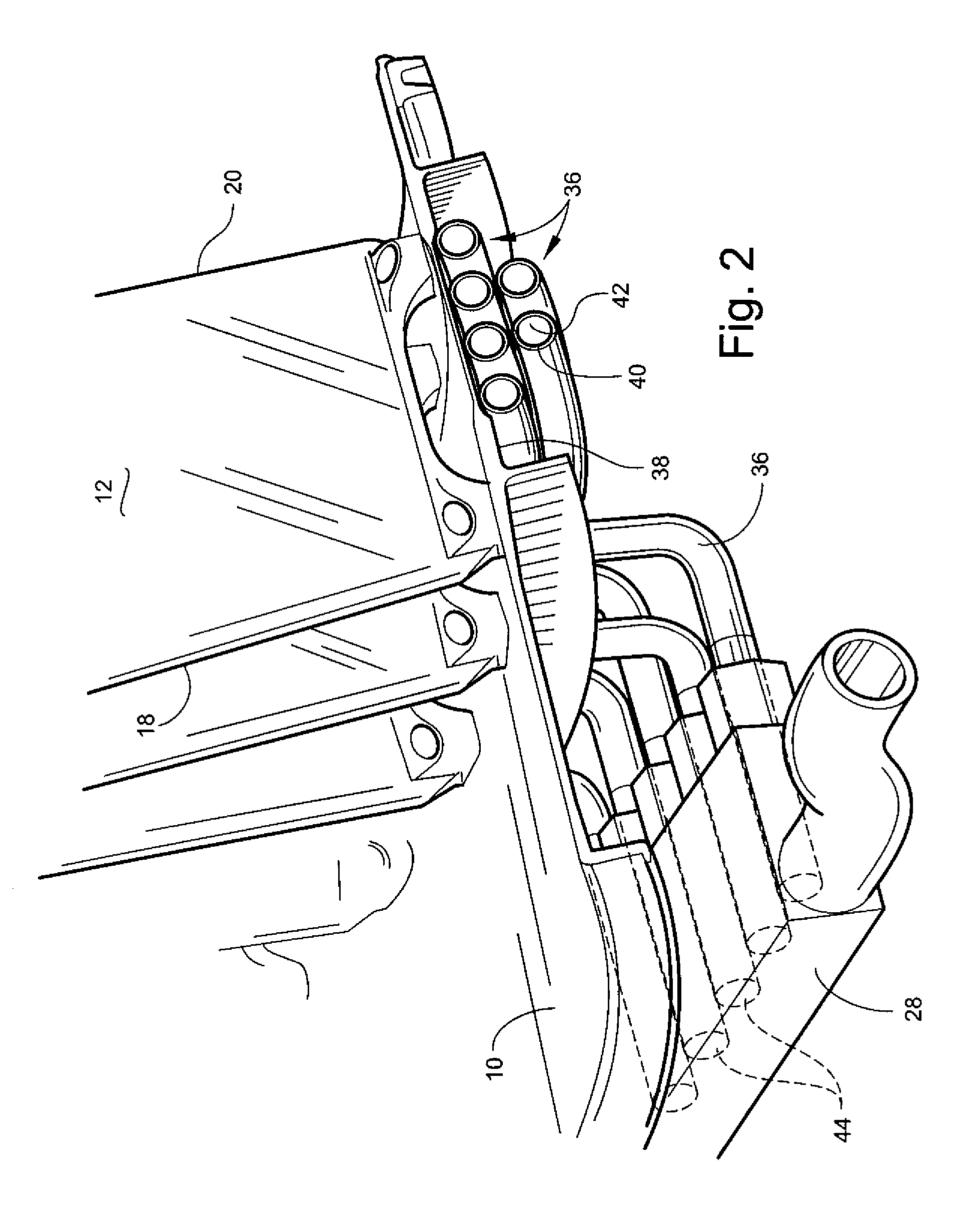
Figure 3
Abstract
Description
BACKGROUND OF THE INVENTION
[0001] This invention relates generally to turbine engines, and more particularly to a system and method using heat pipes for transferring heat within a gas turbine engine.
[0002] Gas turbine engines use pressurized oil to lubricate and cool various components (e.g. bearings, etc.). The oil picks up significant heat in the process which must be rejected to maintain the oil temperature within acceptable limits. Prior art gas turbine engines often employ heat exchangers to cool the engine oil using a relatively cool air stream such as fan discharge air. In turbofan engines, this heat exchanger is often located in the fan duct flow path. This configuration results in a pressure loss and hence a significant fuel burn penalty. It has been estimated that the specific fuel consumption (SFC) penalty associated with this type of configuration can be as high as 1%. There are also cost and weight penalties associated with this configuration.
[0003] In addition, in some en...
Examples
Embodiment Construction
[0014]Referring to the drawings wherein identical reference numerals denote the same elements throughout the various views, FIGS. 1-3 illustrate a portion of a fan module of a gas turbine engine, including an annular fan casing 10. A plurality of outlet guide vanes (OGVs) 12 are connected to and disposed within the fan casing 10. Each of the OGVs 12 (also shown in FIG. 2) has a root 14, a tip 16, a leading edge 18, a trailing edge 20, and opposed sides 22 and 24. The OGVs 12 are airfoil-shaped and are positioned and oriented to remove a tangential swirl component from the air flow exiting an upstream fan (not shown). In the illustrated example, the OGVs also serve as structural members (sometimes referred to as “fan struts”) which connect the fan casing to an inner housing 26. However, in other engine configurations, these functions may be served by separate components. The heat transfer system described herein is equally applicable to OGVs, fan struts, and all other types of genera...