Heat exchanger

a heat exchanger and heat exchanger technology, applied in the field of heat exchangers, can solve the problems of large amount of compressed air, high cost, and high noise and dust hazards for operators, and achieve the effect of enhancing heat transfer and reducing pressure drop

Active Publication Date: 2011-03-08
ENPOT HLDG LTD
View PDF9 Cites 42 Cited by
  • Summary
  • Abstract
  • Description
  • Claims
  • Application Information

AI Technical Summary

Benefits of technology

[0043]In a second embodiment, the method may include mounting a plurality of ducts of the heat transfer arrangement at spaced intervals along the furnace, adjacent a wall of the furnace, and connecting a plurality of the ducts to the conduit by at least one manifold. Further, the method may include shaping an entry opening of each duct to reduce a pressure drop associated with entry of cooling fluid into the duct. In addition, the method may include connecting an exit opening of the duct to the manifold. Also, the method may include providing natural convective flow when no assisted flow is present by allowing escape of some of the cooling fluid to atmosphere through a secondary exit opening defined in each duct.
[0044]The method may include enhancing heat transfer between the duct, which is in the form of a tube, and the furnace by passing the fluid through an aperture defined in a wall of the tube.
[0045]The method may include mounting a shielding element in spaced relationship relative to a wall of the furnace for shielding those parts of a structure in which the furnace to be cooled is located, arranged on an opposite side of the shielding element from the furnace, from radiation heat transfer from the furnace. Then, the method may include passing the fluid through a channel defined between the shielding element and the wall of the furnace to aid in natural convective heat transfer from the wall of the furnace to those parts of the heat transfer arrangement arranged within the channel.

Problems solved by technology

This requires very large amounts of compressed air, is extremely inefficient and generates noise and dust hazards for the operators.
Moreover, the air can only be applied in this way to the overheated localised parts of a furnace shell.
This is economically disadvantageous as any down time of the smelter has adverse economic consequences.
More importantly, when a furnace is shut down for any significant length of time, the electrolyte solidifies resulting in major start up procedures having to be effected in order to restart the furnace.

Method used


Image

  • Heat exchanger
  • Heat exchanger
  • Heat exchanger

Examples


first embodiment

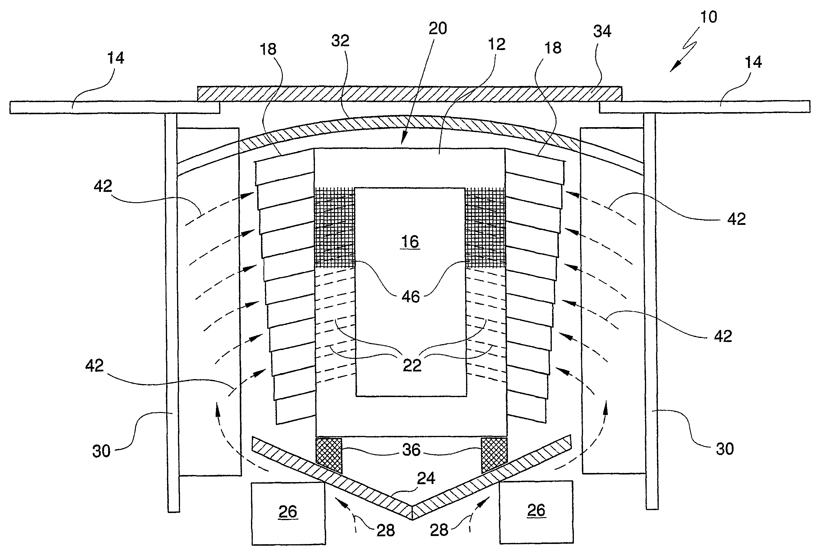
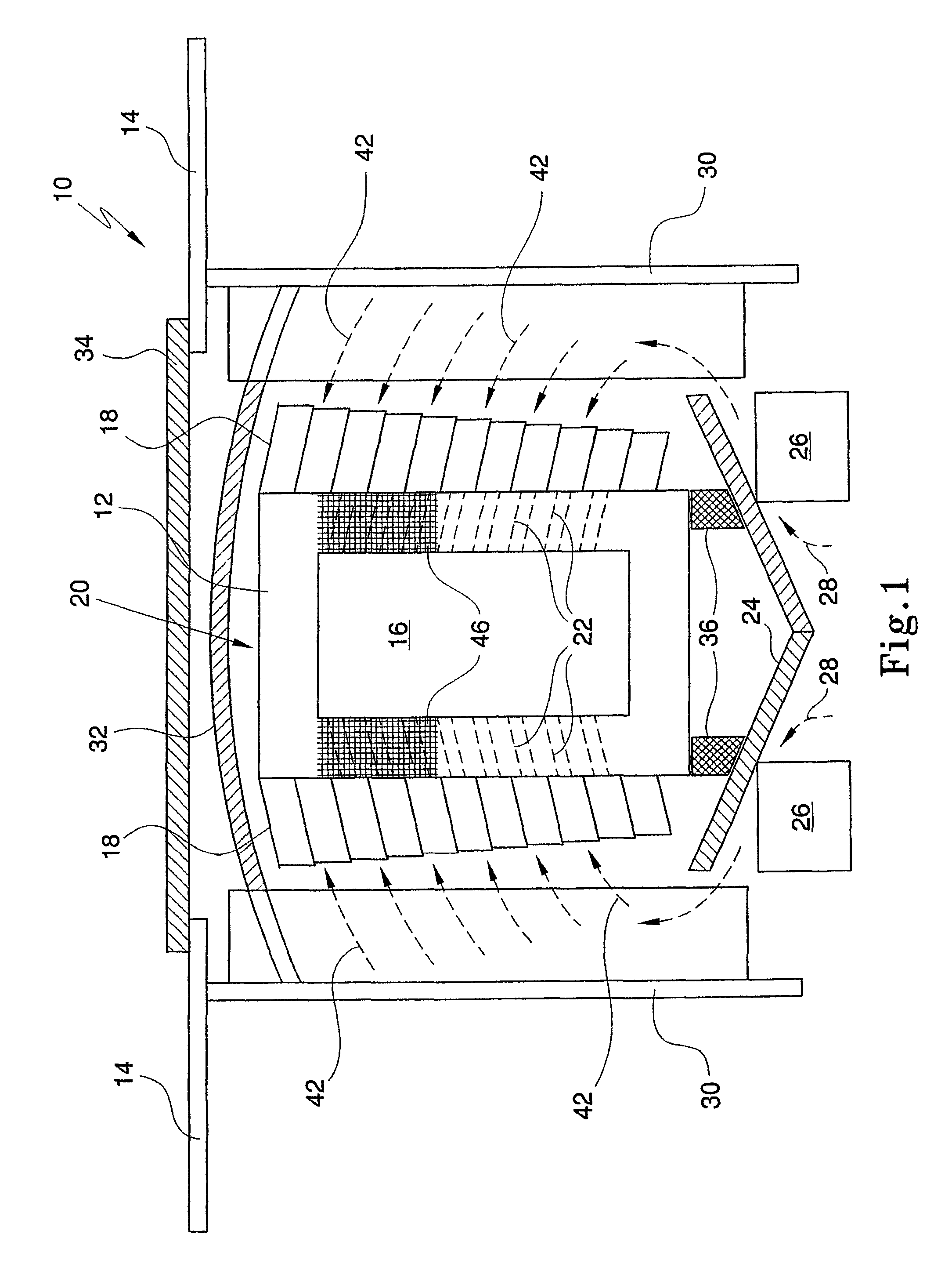
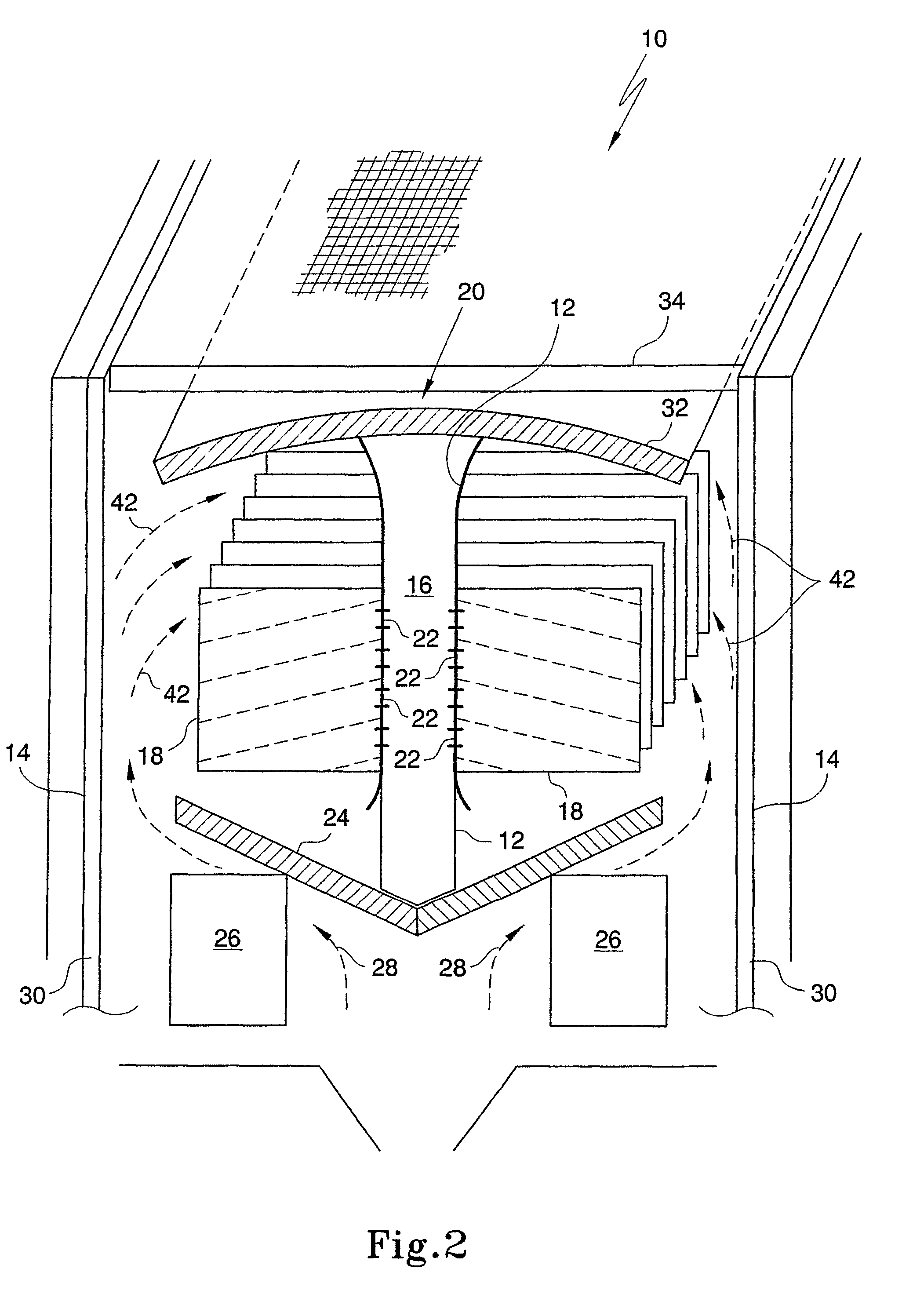
[0077]In FIGS. 1 to 6 of the drawings, reference numeral 10 generally designates a heat exchanger, in accordance with the invention. The heat exchanger 10 includes a conduit 12 which, in use, is arranged between two bodies, in the form of furnaces, illustrated schematically at 14, to be cooled. The conduit 12 defines a passage 16.

[0078]A heat transfer arrangement in the form of a plurality of spaced fins 18 is attached to an exterior surface of the conduit 12. An assembly comprising the conduit 12 and the fins 18 is referred to below, for ease of explanation, as a duct 20.

[0079]In the embodiment illustrated in FIG. 1 of the drawings, the fins 18 are vertically spaced and substantially horizontally disposed or at a slight angle to the horizontal.

[0080]The duct 20 is of a heat absorbing material. More particularly, the duct 20 is of an aluminium material and is coated with a heat absorbing material to enhance the heat absorption characteristics of the duct 20. For example, the duct 20...

second embodiment

[0103]Referring to FIGS. 7 to 14 of the drawings, the heat exchanger 10 is illustrated and described. With reference to the previous drawings, like reference numerals refer to like parts, unless otherwise specified. In the example shown in FIG. 7 of the drawings, the heat exchanger 10 comprises two banks 60 of heat exchanger sections 62. The heat exchanger sections 62 are connected via duct branches 64 and duct connectors 66 to the conduit 12 defining the passage 16. In the version shown in FIG. 7 of the drawings, the conduit 12 is maintained at basement level and exits outside a furnace building out of a work zone of operators of the furnace. Thus, air heated in the heat exchanger 10 is discharged, as indicated by arrow 68, through the passage 16 of the conduit 12.

[0104]Referring to FIG. 8 of the drawings, once again, the heat exchanger 10 is made up of two banks 60 of heat exchanger sections 62. In this embodiment, each bank 60 is bifurcated to have two stacks 70, one at each end ...


PUM

PropertyMeasurementUnit
temperaturesaaaaaaaaaa
width aspect ratioaaaaaaaaaa
heat absorptionaaaaaaaaaa

Abstract

A heat exchanger 10 includes a conduit 12 for conveying cooling fluid relative to a body to be cooled. A heat transfer arrangement 62 is arranged in communication with an interior of the conduit 12, the heat transfer arrangement 62 and the conduit 12 together defining an assembly that is mountable adjacent the body to be cooled, convective heat exchange occurring, in use, due to movement of the cooling fluid relative to the body and the heat transfer arrangement 62 of the assembly and radiant heat exchange occurring between the body and at least part of the heat transfer arrangement 62 of the assembly.

Description

CROSS-REFERENCE TO RELATED APPLICATIONS[0001]This application is a national stage filing under 35 U.S.C. 371 of International Application PCT / NZ2005 / 000101 filed May 16, 2005, which claims priority from New Zealand Application No. 533006 filed May 18, 2004. The entire teachings of the referenced application is incorporated herein by reference. International Application PCT / NZ2005 / 000101 was published under PCT Article 21(2) in English.FIELD OF THE INVENTION[0002]This invention relates to a heat exchanger. The invention relates particularly, but not necessarily exclusively, to a heat exchanger for use in the cooling of furnaces of metalliferous smelters. It will readily be appreciated that the heat exchanger could be used in a wide range of other applications as well.BACKGROUND TO THE INVENTION[0003]In metalliferous smelters and, in particular, aluminium smelters, the smelter comprises a plurality of pots or furnaces, each having a shell within which an electrolyte and molten metal a...

Claims


Application Information

Patent Timeline
Patent Type & Authority Patents(United States)
IPC IPC(8): C21C5/00C21B7/10C21B9/10C21C5/46F27D1/12F27D9/00
CPCC21B7/106C21C5/4646C25C3/085F27D9/00F27D2009/0005F27D2009/0013Y02P10/134Y02P10/25
Inventor TAYLOR, MARK P.CHEN, JOHN J JFARID, MOHAMEDWALLACE, ROBERT JOHN
Owner ENPOT HLDG LTD
Why Eureka
Try Eureka