Adjusting optical properties of optical thin films

a technology of optical thin films and optical properties, applied in the field of optical devices, can solve problems such as additive or subtractive interference, and achieve the effects of increasing the sensitivity of optical thin films, enhancing, increasing, heightening, and stimulating the response of layers

Inactive Publication Date: 2011-03-08
CIRREX SYST
View PDF221 Cites 84 Cited by
  • Summary
  • Abstract
  • Description
  • Claims
  • Application Information

AI Technical Summary

Benefits of technology

[0020]In one aspect of the present invention, applying energy, such as thermal energy or ultraviolet light, to an optical thin film can adjust an optical property of the thin film and can alter at least some aspect of the optical thin film's interference of light. An application of energy can adjust the refractive index of the optical thin film or the speed that light propagates in the optical thin film. An energy application can also cause a change in the optical thickness of the optical thin film.
[0021]In another aspect of the present invention, a chemical, additive, moiety, or agent of an optical thin film can increase the sensitivity of the optical thin film to an application of ultraviolet light. The agent can be nitrogen, hydrogen, germanium, or other material. The composition of the optical thin film can include silicon dioxide and / or silicon oxynitride. The optical thin film can be a dielectric thin film.
[0022]In yet another aspect of the present invention, a method for fabricating an optical thin film can include producing at least one optical thin film layer in a deposition chamber. The resulting optical thin film layer can be a layer in an antireflective coating on a laser or other optical device or a layer in an optical filter. Exposing the layer to a dose of ultraviolet light can alter the refractive index of the optical thin film layer. Subjecting the layer to hydrogen can enhance, increase, heighten, stimulate, cause, or promote the layer's response to the dose.

Problems solved by technology

The reflected portions of light from each surface can interact or interfere with one another as wave phenomena, resulting in additive or subtractive interference.

Method used


Image

  • Adjusting optical properties of optical thin films
  • Adjusting optical properties of optical thin films
  • Adjusting optical properties of optical thin films

Examples


Embodiment Construction

[0056]The present invention is directed to adjusting one or more optical properties of an optical thin film. Adjusting an optical property of an optical thin film can facilitate efficient and cost-effective fabrication of optical systems such as thin film optical filters that manipulate light based on thin film interference. An optical thin film adjustment can also create spatially specific optical properties or patterns in an optical thin film.

[0057]Turning now to discuss each of the drawings presented in FIGS. 1-27, in which like numerals indicate like elements through the several figures, an exemplary embodiment of the present invention will be described in detail.

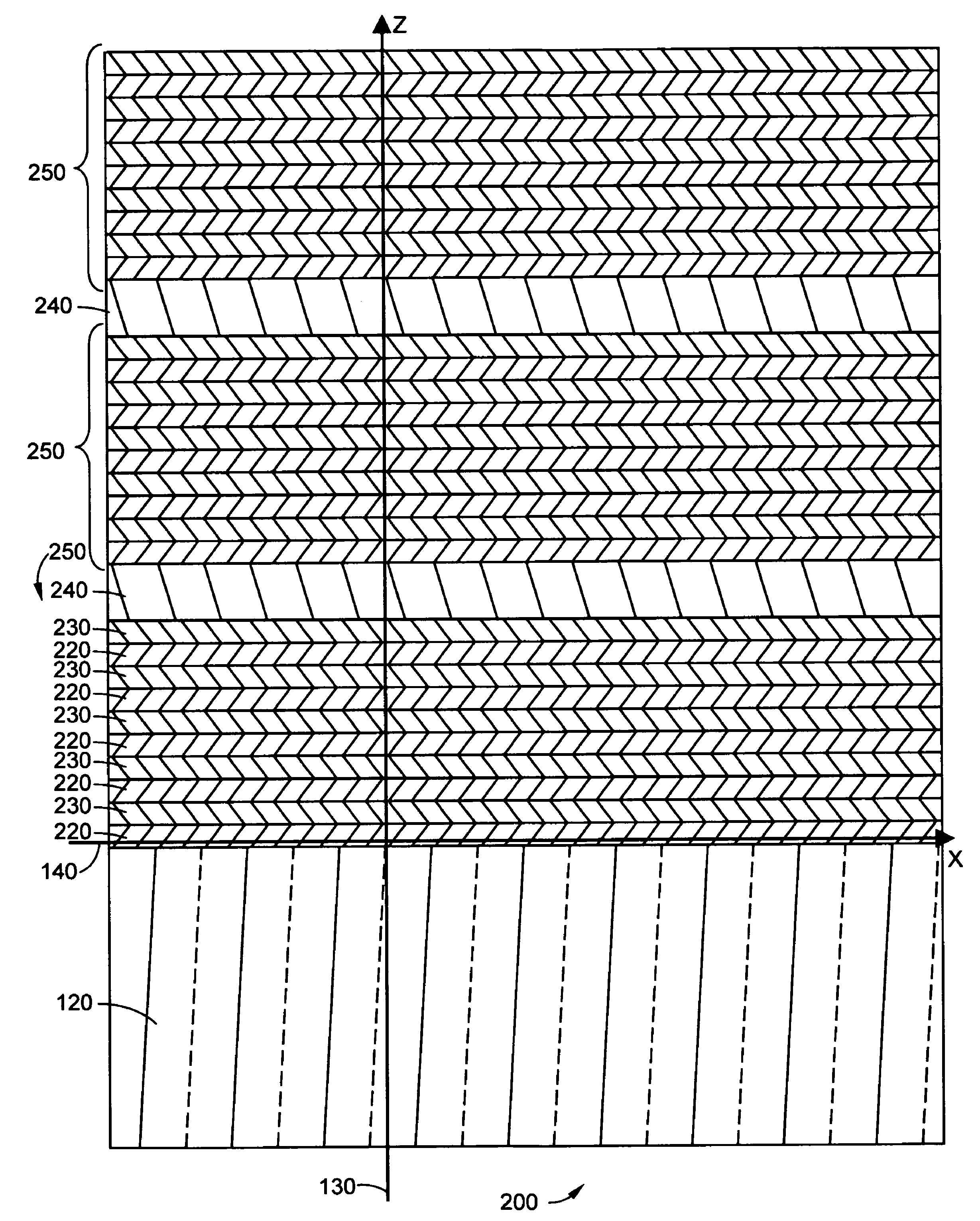
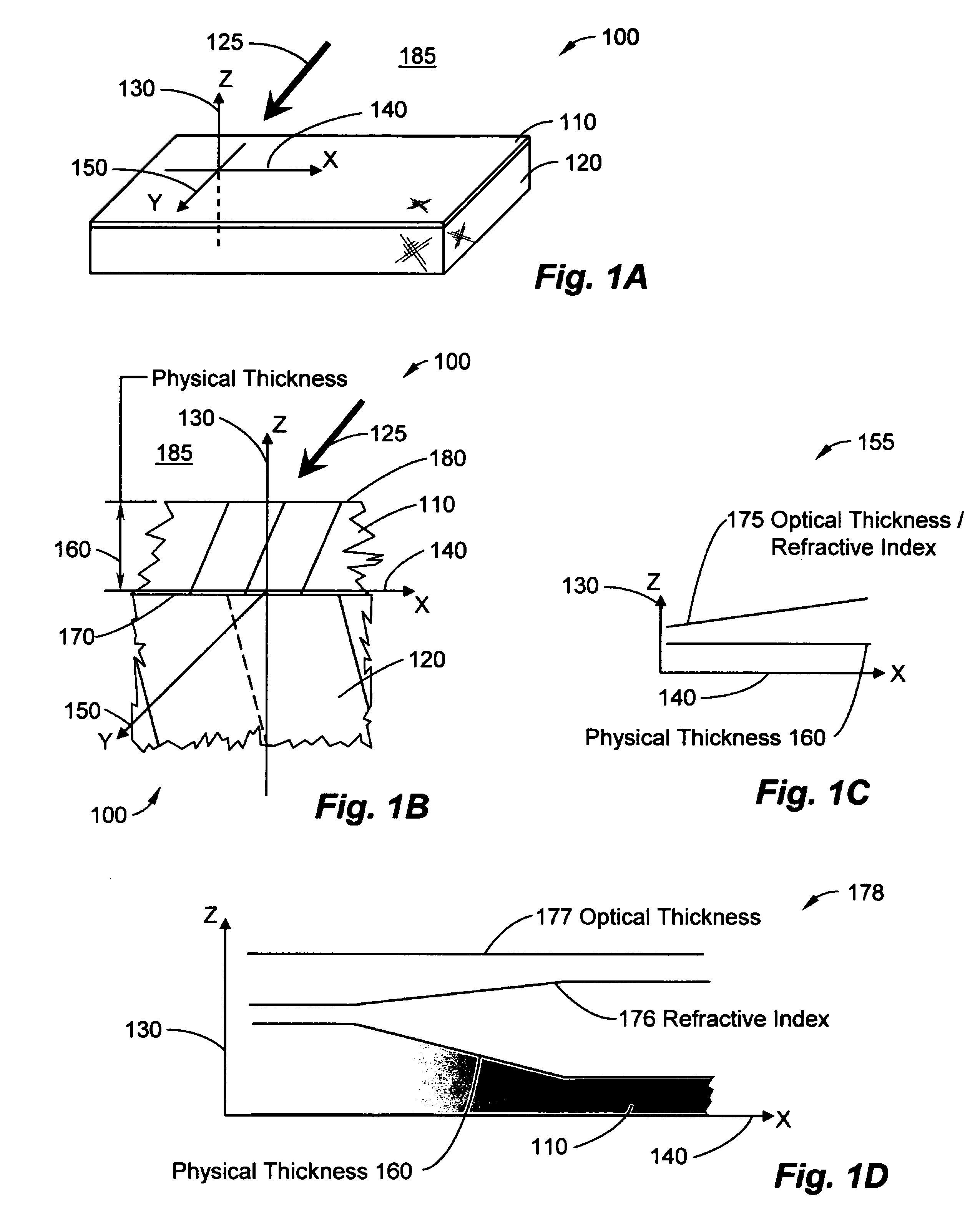
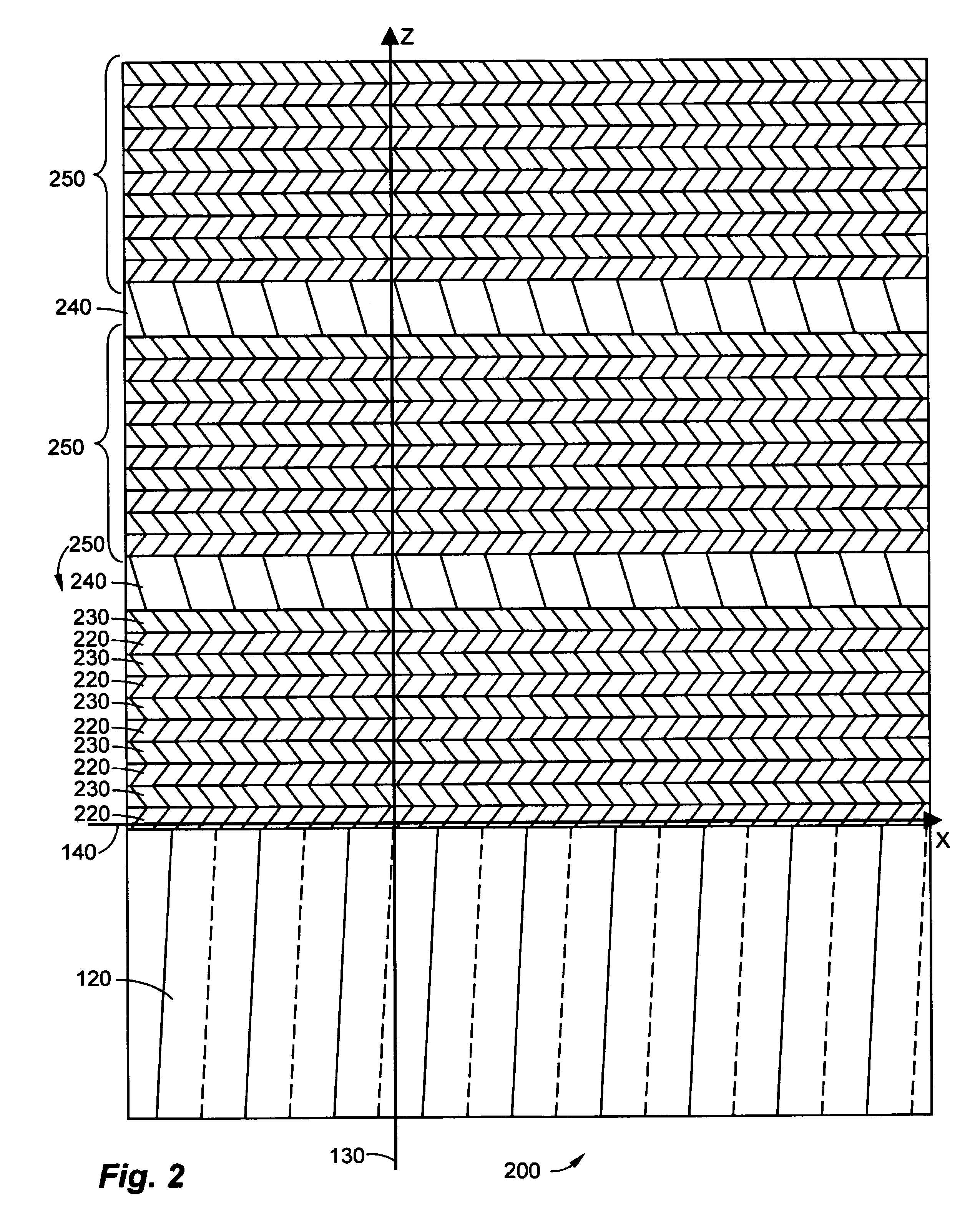
[0058]FIGS. 1A and 1B illustrate a thin film optical system 100 having an optical thin film 110 adhering to a substrate 120 in accordance with an exemplary embodiment of the present invention. A Cartesian coordinate system, having an x-axis 140, a y-axis 150, and a z-axis 130, illustrates the relative orientation of the...


PUM


Abstract

An optical thin film can have a refractive index variation along a dimension that is perpendicular to its thickness. Two areas that have equal physical thicknesses can have different optical thicknesses. Including the thin film as a layer in a thin film optical filter can provide a corresponding variation in the filter's spectral properties. Dosing an optical thin film with ultraviolet light can cause the refractive index variation. Subjecting the film to hydrogen can increase the refractive index's response to the dose of light. Dosing a region of a thin film optical filter with ultraviolet light can change the spectral properties of the region, for example shifting an out-of-specification optical filter into specification thereby increasing manufacturing yield. An agent can promote the film's response to the dose.

Description

CROSS REFERENCE TO RELATED APPLICATIONS[0001]This application claims the benefit of priority to U.S. Provisional Patent Application Ser. No. 60 / 570,258, entitled “Adjusting Optical Properties of Optical Thin Films,” and filed May 12, 2004. The contents of U.S. Provisional Patent Application Ser. No. 60 / 570,258 are hereby incorporated by reference.TECHNICAL FIELD[0002]The present invention relates to optical devices and more specifically to adjusting an optical property, such as refractive index, of an optical thin film, thin film optical filter, or thin film optical system by an application of short-wavelength light energy or other energy.BACKGROUND OF THE INVENTION[0003]Optical thin films are useful for a wide range of optical applications such as antireflective (“AR”) coatings, high-reflective (“HR”) coatings, dielectric mirrors, and thin film interference filters. Compact size and environmental stability are two properties of optical thin films that have stimulated their deployme...

Claims


Application Information

Patent Timeline
Patent Type & Authority Patents(United States)
IPC IPC(8): G02B6/02
CPCG02B5/285G02B5/289G02B5/288G02B5/28G02B6/264
Inventor WACH, MICHAEL L.
Owner CIRREX SYST
Why Eureka
Try Eureka