Method of making a balloon catheter shaft having high strength and flexibility

a balloon catheter and high-flexibility technology, applied in the field of medical devices, can solve the problems that the orientation does not significantly increase the bending stiffness of the tubular member, and achieve the effects of low bending stiffness, high rupture pressure, and high tensile strength

Inactive Publication Date: 2011-03-15
ABBOTT CARDIOVASCULAR
View PDF235 Cites 107 Cited by
  • Summary
  • Abstract
  • Description
  • Claims
  • Application Information

AI Technical Summary

Benefits of technology

[0006]This invention is directed to a catheter having an elongated shaft with a tubular member which forms at least a portion of the shaft and which is formed of a biaxially oriented thermoplastic polymeric material. One aspect of the invention is directed to a method of forming the catheter shaft by radially and longitudinally expanding the tubular member to biaxially orient the polymeric material. A catheter of the invention preferably has an improved combination of low bending stiffness, high rupture pressure, and high tensile strength, for improved catheter performance.
[0007]A method of making a catheter shaft of the invention generally comprises radially and longitudinally expanding an extruded tube, which results in an expanded tubular member having a higher rupture pressure and tensile strength than a tube extruded directly to the same final dimensions (i.e., wall thickness and outer diameter) as the expanded tubular member. It is believed that the radial and longitudinal expansion circumferentially and longitudinally orients the polymeric structure within the material. However, the orientation does not significantly increase the bending stiffness of the tubular member. Thus, a relatively low durometer polymer can be selected to minimize bending stiffness in the radially and axially deformed tubular member. The inherently low bending stiffness of the low durometer polymer provides a longitudinally flexible shaft tubular member which more readily bends during maneuvering of the catheter within the patient.
[0008]In a presently preferred embodiment, the catheter is a balloon catheter generally comprising an elongated shaft having a proximal end, a distal end, an inflation lumen extending therein, and a tubular member which has the inflation lumen therein and which is formed of a biaxially oriented nonporous thermoplastic polymer, and a balloon sealingly secured to a distal shaft section. In one embodiment, the balloon is a relatively high pressure balloon. The biaxially oriented polymer has polymer chains oriented longitudinally along the tubular member for increased tensile strength, and circumferentially around the tubular member for increased rupture pressure. The high tensile strength of the shaft tubular member improves catheter performance by, for example, increasing the ability to safely pull the catheter from within the patient's vessel without tearing apart / damaging the catheter, e.g., during retrieval of the catheter lodged in a calcific lesion.
[0009]The balloon has an interior in fluid communication with the inflation lumen, and a rupture pressure which is significantly less than the rupture pressure of the shaft tubular member. As a result, the balloon catheter preferably has a failure mode in which the balloon will rupture before the pressure-containing catheter shaft tubular member, to prevent or minimize vessel injury in the event of a catheter rupture. In one embodiment, the balloon is a relatively high pressure balloon, for example having a rupture pressure of at least about 20 atm or more. The shaft tubular member preferably has a mean rupture strength substantially greater than that of the balloon, so that the distribution of the two rupture pressure ranges have essentially no statistical overlap.
[0014]In the design of shafts for balloon catheters, extruded catheter shaft tubing is conventionally resized to a smaller diameter and wall thickness by necking the tubing using a die and mandrel. Unlike such conventional necking procedures which force the tubing through a die and thus primarily elongate the tubing with only a minimal decrease in tubing diameter and / or wall thickness, the catheter shaft tubing of the invention is highly circumferentially oriented by being radially expanded to an inner diameter significantly larger than the original (extruded) inner diameter. In one embodiment, the tubing is radially expanded to substantially the maximum amount possible (based on the polymeric material and extruded tubing dimensions), which results in expanded tubing having minimal radial growth at increasing inner pressures. Consequently, the expanded tubing has an improved controlled failure mode. In the event that the shaft tubing is over-pressurized above the rupture pressure of the shaft tubing, the expanded tubing preferably fails by rupturing with a small longitudinally extending slit and without radially expanding against the vessel wall, which thus prevents or minimizes vessel injury.
[0015]The invention provides a catheter shaft tubular member having an improved combination of low bending stiffness, high rupture pressure, and high tensile strength. Preferably, a catheter shaft tubular member of the invention has a low profile and high flexibility such that the catheter has excellent ability to track and to cross tight, tortuous anatomy, while having a high rupture pressure and the ability to maintain inflation lumen integrity during a medical procedure. The high rupture pressure catheter shaft assures that inadvertent over-pressurization will normally result in rupture within the balloon (and most notably even a relatively high rupture pressure balloon) at the treatment site rather than elsewhere in the patient's vasculature. Unlike conventional catheter design in which shaft sections requiring minimized profile and / or maximized lumen size are typically formed of high strength / stiffness materials to allow for the shaft to be formed with thin walls, the catheter shaft section of the invention is formed of a relatively low durometer polymeric material providing a low bending stiffness. Similarly, unlike shaft sections formed with multiple layers or reinforcements to increase the burst pressure / strength of the shaft, the catheter shaft section of the invention has relatively thin walls, for minimizing the shaft profile while maximizing the shaft lumen size, and for minimizing the shaft bending stiffness.

Problems solved by technology

However, the orientation does not significantly increase the bending stiffness of the tubular member.

Method used


Image

  • Method of making a balloon catheter shaft having high strength and flexibility
  • Method of making a balloon catheter shaft having high strength and flexibility

Examples


example

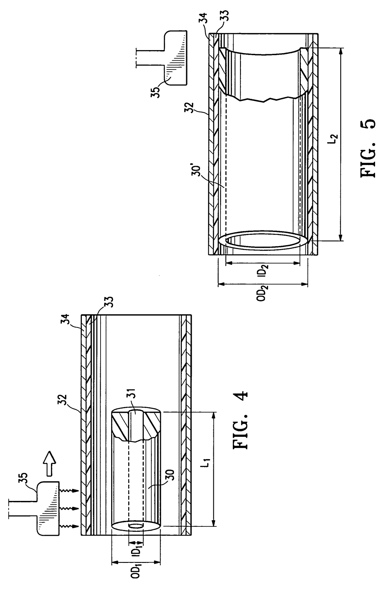
[0041]PEBAX 63D was used to extrude four sets of multiple tubing samples (N=5) having an extruded inner diameter (ID) of about 0.005 inches, and an extruded outer diameter (OD) ranging from about 0.0217 inches to about 0.0264 inches. The extruded tubing was placed inside a stainless steel capture tube having a Teflon liner with an ID of about 0.034 inches, and radially and axially expanded therein at an elevated temperature. Specifically, a vertical hot air necking apparatus was used to pressurize the tubing with pressurized air at about 500 psi and to simultaneously lengthen the tubing with an axial load pulling on one end of the tubing, while the tubing was heated within the capture tube using a heating nozzle traversing along the outside of the capture tube at a set point of about 385° F. (196° C.) (the temperature within the inner chamber of the capture tube is typically less than the set point, and depends upon factors such as the nozzle temperature set point, the nozzle speed,...


PUM

PropertyMeasurementUnit
inner diameteraaaaaaaaaa
tensile strengthaaaaaaaaaa

Abstract

A catheter having an elongated shaft with a tubular member which forms at least a portion of the shaft and which is formed of a biaxially oriented thermoplastic polymeric material, and a method of forming the catheter shaft by radially and longitudinally expanding the tubular member to biaxially orient the polymeric material. A catheter of the invention has an improved combination of low bending stiffness, high rupture pressure, and high tensile strength, for improved catheter performance.

Description

FIELD OF THE INVENTION[0001]This invention generally relates to medical devices, and particularly to intracorporeal devices for therapeutic or diagnostic uses, such as balloon catheters.BACKGROUND OF THE INVENTION[0002]In percutaneous transluminal coronary angioplasty (PTCA) procedures, a guiding catheter is advanced until the distal tip of the guiding catheter is seated in the ostium of a desired coronary artery. A guidewire, positioned within an inner lumen of a dilatation catheter, is first advanced out of the distal end of the guiding catheter into the patient's coronary artery until the distal end of the guidewire crosses a lesion to be dilated. Then the dilatation catheter having an inflatable balloon on the distal portion thereof is advanced into the patient's coronary anatomy, over the previously introduced guidewire, until the balloon of the dilatation catheter is properly positioned across the lesion. Once properly positioned, the dilatation balloon is inflated with fluid ...

Claims


Application Information

Patent Timeline
Patent Type & Authority Patents(United States)
IPC IPC(8): B29C39/02B29C43/02B29C49/00B29C71/00B29C45/00B29C47/00B29C49/08B29C67/00B29D22/00B29C35/02A61M29/00A61F2/958
CPCA61M25/0009B29C49/0073B29C49/04B29C55/26A61M25/10Y10S264/90B29C49/10B29C65/02B29C65/48B29K2101/12B29K2995/0053B29L2022/022B29L2031/7542Y10S264/903B29C66/5344B29B2911/14586Y10S264/904B29C2949/081B29C49/071
Inventor WILSON, BRUCE M.DURCAN, JONATHAN P.SIMPSON, JOHN A.
Owner ABBOTT CARDIOVASCULAR
Why Eureka
Try Eureka