Particle trap for a plasma source

a plasma source and particle trap technology, applied in the direction of plasma technique, chemical/physical process, chemical vapor deposition coating, etc., can solve the problem of often generated particles, reduce particle counts, minimize the introduction of particles or defects, and achieve the effect of reducing particle counts

Inactive Publication Date: 2011-03-29
MKS INSTR INC
View PDF24 Cites 2 Cited by
  • Summary
  • Abstract
  • Description
  • Claims
  • Application Information

AI Technical Summary

Benefits of technology

[0005]The invention generally features apparatus and methods that can provide reduced particle counts in an activated gas. One advantage is that the invention minimizes the introduction of particles or defects on the material (e.g., a semiconductor wafer) to be processed. Another advantage is that the invention provides a higher yield rate in the manufacturing of materials to be processed (e.g., a semiconductor wafer). Yet another advantage is that the invention provides an apparatus that can be replaceable to minimize manufacturing downtime. Another advantage is that the invention reduces particle count while minimizing recombination of the activated gas.

Problems solved by technology

A known problem in the art of plasma generation is that particles are often generated which can, for example, contaminate the plasma generator or chambers coupled to an output of the plasma chamber.

Method used


Image

  • Particle trap for a plasma source
  • Particle trap for a plasma source
  • Particle trap for a plasma source

Examples


Embodiment Construction

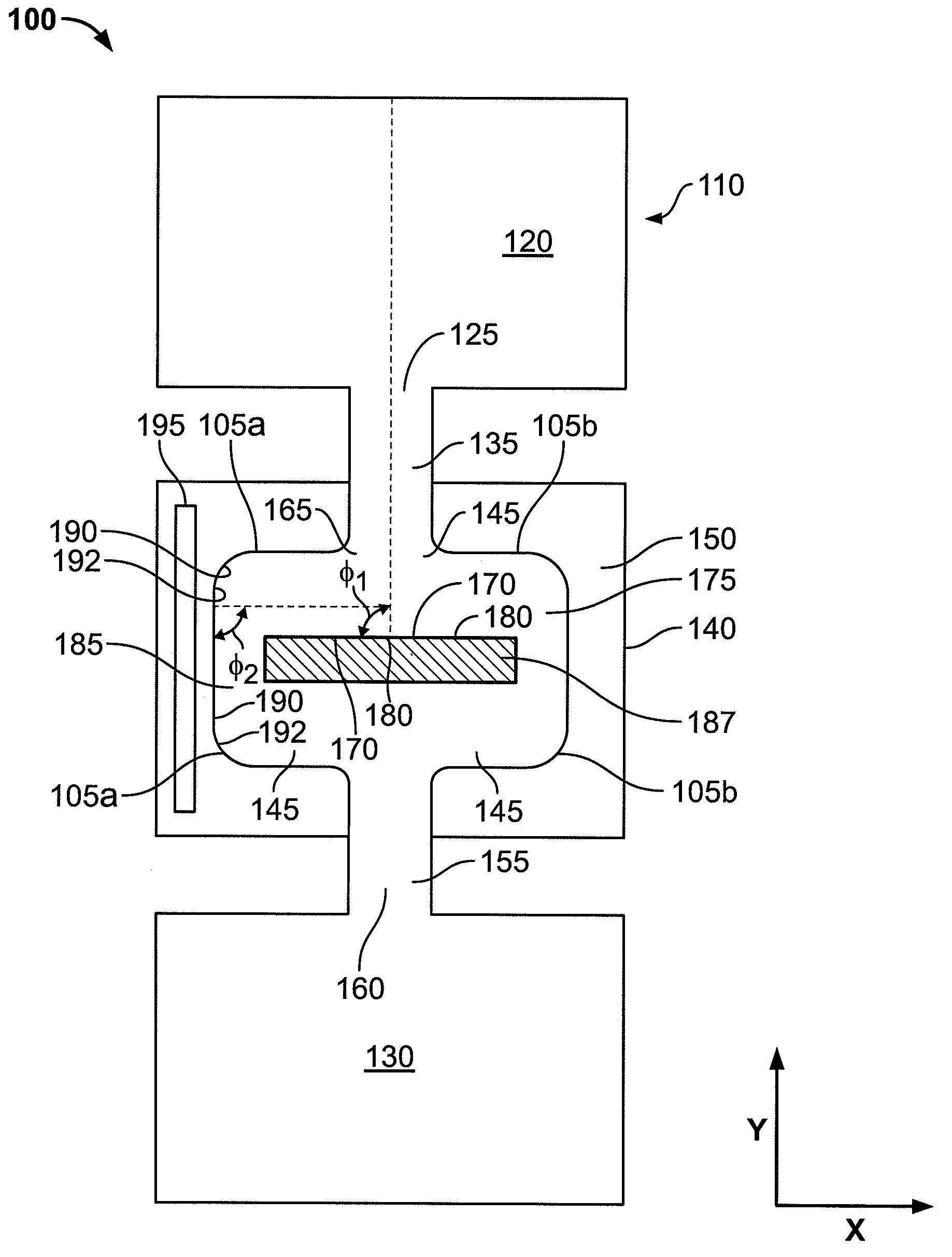
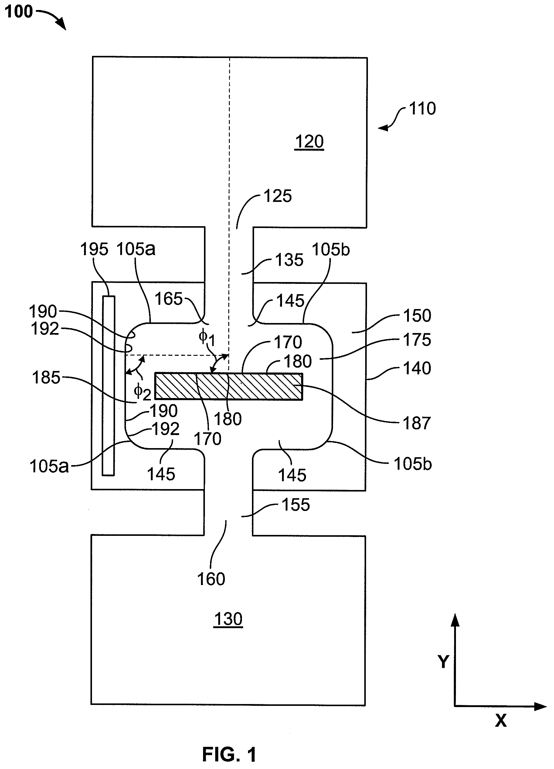
[0035]FIG. 1 is a schematic cross-sectional view of a plasma generation system 100, according to an illustrative embodiment of the invention. The system 100 includes a remote plasma source 110, a process chamber 130, and a particle trap 140. An outlet 125 of the remote plasma source 110 is coupled to an inlet 135 of the particle trap 140. In some embodiments, the outlet 125 is directly coupled to the inlet 135. In some embodiments, the outlet 125 is indirectly coupled to the inlet 135 by, for example, a conduit or other suitable structure. The plasma is produced in a chamber 120 of the plasma source 110 by, for example, applying an electric potential of sufficient magnitude to a plasma gas (e.g., O2, N2, Ar, NF3, H2 and He), or a mixture of gases, to ionize at least a portion of the gas in the chamber 120. The plasma is used to activate additional gases introduced into the chamber 120 of the plasma source 110, placing the additional gases in an activated state such that the gases ha...


PUM

PropertyMeasurementUnit
angleaaaaaaaaaa
angle Φ1aaaaaaaaaa
angle θ1aaaaaaaaaa

Abstract

A particle trap for a remote plasma source includes a body structure having an inlet for coupling to a chamber of a remote plasma source and an outlet for coupling to a process chamber inlet. The particle trap for a remote plasma source also includes a gas channel formed in the body structure and in fluid communication with the body structure inlet and the body structure outlet. The gas channel can define a path through the body structure that causes particles in a gas passing from a first portion of the channel to strike a wall that defines a second portion of the gas channel at an angle relative to a surface of the wall. A coolant member can be in thermal communication with the gas channel.

Description

FIELD OF THE INVENTION[0001]The invention relates generally to plasma generation and processing equipment. In particular, the invention relates to methods and apparatus for removing contaminant particles from an activated gas.BACKGROUND[0002]Plasmas are often used to activate gases placing them in an activated state such that the gases have an enhanced chemical reactivity. In some cases, the gases are activated to produce dissociated gases containing ions, free radicals, atoms and molecules. Dissociated gases are used for numerous industrial and scientific applications including processing solid materials such as semiconductor wafers, powders, and other gases. Properties of activated gases and conditions under which materials are exposed to the gases vary widely depending on the application. Significant amounts of power are sometimes required in the plasma for dissociation to occur.[0003]Plasma sources generate plasmas by, for example, applying an electric potential of sufficient ma...

Claims


Application Information

Patent Timeline
Patent Type & Authority Patents(United States)
IPC IPC(8): B01D46/46
CPCH01J37/32357H01J37/32871Y10T29/4935Y10S55/15H05H1/24H05H1/28
Inventor SHAJII, ALICHEN, XINGCOWE, ANDREWBURTNER, DAVIDENTLEY, WILLIAM ROBERTSHAO, SHOUQIAN
Owner MKS INSTR INC
Why Eureka
Try Eureka