Cross polarization interference canceling method and cross polarization interference canceling apparatus

a technology of interference canceling and cross polarization, applied in pulse manipulation, pulse technique, depolarization effect reduction, etc., can solve the problems of reducing and reducing the reliability of communication paths, so as to reduce reduce the time constant of xpic correspondingly greater, control can be made small, and the effect of reducing the influence of phase nois

Inactive Publication Date: 2011-04-12
NEC CORP
View PDF20 Cites 7 Cited by
  • Summary
  • Abstract
  • Description
  • Claims
  • Application Information

AI Technical Summary

Benefits of technology

[0025]On the other hand, the reference synchronization scheme in which the local oscillator that is provided for each polarization receiver is frequency-synchronized based on the signal from a reference oscillator has an advantage that if one local oscillator breaks down, the communication path via the other polarization can be secured. However, though either local oscillator provided for each polarization receiver is frequency-synchronized based on the signal from the reference oscillator, the phase noise involved in each local oscillator is irrelevant from the other. Accordingly, there occurs the problem that the phase noise from each local oscillator causes characteristic degradation. For improvement against the characteristics deterioration, a high-cost local oscillator that provides low noise phase figure needs to be used.
[0038]Also, when inexpensive RF local oscillators that present relatively large phase noise are used to construct an XPIC of a reference synchronization scheme, it is possible to prevent the lowering of the cross polarization interference canceling capability based on phase noise.

Problems solved by technology

However, because the output from a single local oscillator is branched for use, there is the problem that both communications through the two polarizations shut down all at once if this local oscillator breaks down.
This is disadvantageous in terms of communications path reliability.
However, though either local oscillator provided for each polarization receiver is frequency-synchronized based on the signal from the reference oscillator, the phase noise involved in each local oscillator is irrelevant from the other.
Accordingly, there occurs the problem that the phase noise from each local oscillator causes characteristic degradation.

Method used


Image

  • Cross polarization interference canceling method and cross polarization interference canceling apparatus
  • Cross polarization interference canceling method and cross polarization interference canceling apparatus
  • Cross polarization interference canceling method and cross polarization interference canceling apparatus

Examples


first exemplary embodiment

The First Exemplary Embodiment

[0078]A cross polarization interference canceling apparatus of the first exemplary embodiment of the present invention will be described. FIG. 7 is a block diagram showing an essential part of a cross polarization interference canceling apparatus of the first exemplary embodiment, in which the portion downstream of the outputs from orthogonal demodulators 8 and 11 shown in FIG. 4 is shown. The configuration upstream of orthogonal demodulators 8 and 11 is that shown in FIG. 4. The blocks allotted with the same reference numerals as in the conventional example shown in FIG. 3 have the same functions except that input control signals are partly different.

[0079]First, connection for signal transmission between the components shown in FIG. 7 will be described.

[0080]As shown in FIG. 7, the output side of complex multiplier 18 is connected to adder 19. Connected to the output side of adder 19 is a signal line for transmitting demodulated signals. Carrier phase...

second exemplary embodiment

The Second Exemplary Embodiment

[0113]A cross polarization interference canceling apparatus of the second exemplary embodiment of the present invention will be described. FIG. 11 is a block diagram showing a cross polarization interference canceling apparatus of the second exemplary embodiment of the present invention. The above first exemplary embodiment uses a method of adding the XPIC signal after establishment of carrier synchronization. The second exemplary embodiment, however, uses a method of adding the XPIC signal before establishing carrier synchronization.

[0114]In the present exemplary embodiment, since complex multiplier 18′ at the XPIC 24 output needs to simply correct only the phase difference caused by the influence of the phase noise, the configuration can be correspondingly simplified. Compared to the first exemplary embodiment, the configuration for adding the output from accumulator 22 and the output from accumulator 22′ is omitted as shown in FIG. 11.

[0115]Here, th...

third exemplary embodiment

The Third Exemplary Embodiment

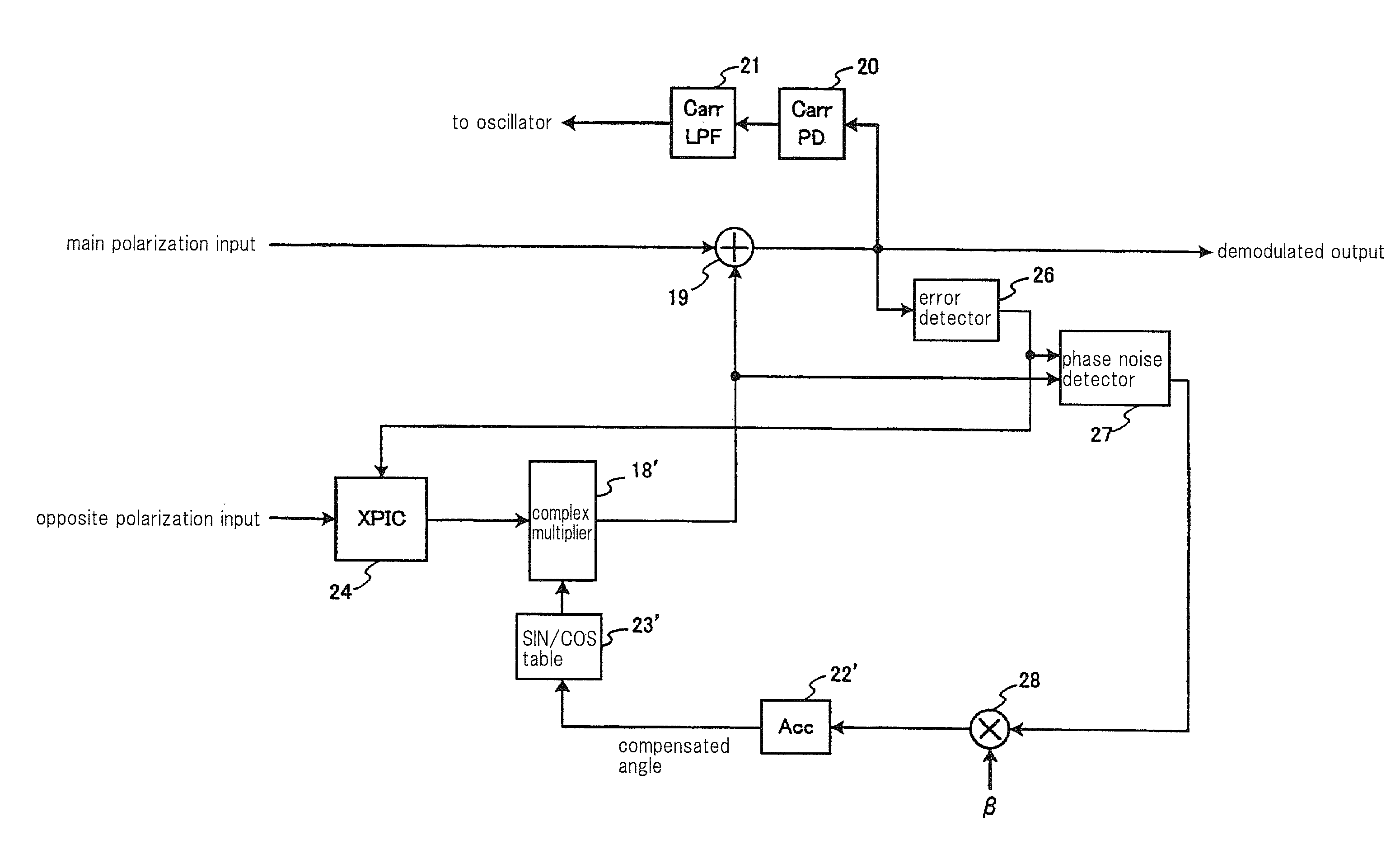
[0116]A cross polarization interference canceling apparatus of the third exemplary embodiment of the present invention will be described. FIG. 12 is a block diagram showing a cross polarization interference canceling apparatus of the third exemplary embodiment of the present invention. The present exemplary embodiment has a configuration in which the complex multiplier 18′ in the second exemplary embodiment is disposed on the input side of XPIC 24. That is, phase compensation can also be performed by changing the phase of the input signal to XPIC 24. In this case, complex multiplier 18′ is arranged before XPIC 24 as shown in FIG. 12.

[0117]FIG. 13 is a flow chart for summarizing the operational sequence of the cross polarization interference canceling method in the present exemplary embodiment. As shown in FIG. 13, error detector 26 determines the error signal that indicates the difference between the demodulated signal and the ideal received signal of t...


PUM


Abstract

A cross polarization interference canceling apparatus of the present invention includes: error detector 26 for extracting a difference between a demodulated signal that is the main polarization signal in which compensation for cross polarization interference has been made and the received signal which indicates an ideal state of the main polarization, and outputting an error signal that indicates the extracted difference; phase noise detector 27 for outputting a phase noise difference by comparing a cross polarization interference compensating signal that is the opposite polarization signal in which compensation for cross polarization interference has been made with the error signal; a control signal generator for generating a control signal corresponding to the phase noise difference; and phase rotator 18′ disposed prior to, or posterior to, a cross polarization interference canceller for generating the cross polarization interference compensating signal, for controlling the phase of the cross polarization interference compensating signal in such a direction as to suppress the phase noise difference, in response to the input of the control signal.

Description

TECHNICAL FIELD[0001]The present invention relates to a technology for canceling interference between cross polarized waves, in particular, relating to a preferable cross polarization interference canceling method and cross polarization interference canceling apparatus that are suitably used for transmission equipment of a co-channel transmission system in fixed microwave communications and the like.BACKGROUND ART[0002]As a method for canceling cross polarization interference in transmission equipment of a co-channel transmission system or the like, an XPIC (Cross polarization interference Canceller) has been used (see Japanese Patent Application Laid-open 2000-165339: this publication will be referred to hereinbelow as patent document 1). This scheme performs cancellation of cross polarization interference by generating a signal that cancels the interference signal from an orthogonal polarization wave (which will be referred to hereinbelow as opposite polarization) relative to an o...

Claims


Application Information

Patent Timeline
Patent Type & Authority Patents(United States)
IPC IPC(8): H04B1/10
CPCH04B1/126H04B1/123H04B7/002
Inventor KAWAI, MASAHIRO
Owner NEC CORP
Why Eureka
Try Eureka