
Data sampling circuit and method for clock and data recovery

a data sampling and data recovery technology, applied in the direction of digital transmission, phase-modulated carrier system, synchronisation signal speed/phase control, etc., can solve the problem of difficulty in clock recovery, the desirability of burst-mode transmission, and the difficulty of nrz format typically presenting a greater difficulty, so as to reduce the effective bandwidth and reduce the effect of economic and practical implementation

Active Publication Date: 2011-04-19
GOFOTON HLDG
View PDF30 Cites 0 Cited by
  • Summary
  • Abstract
  • Description
  • Claims
  • Application Information

AI Technical Summary

Benefits of technology

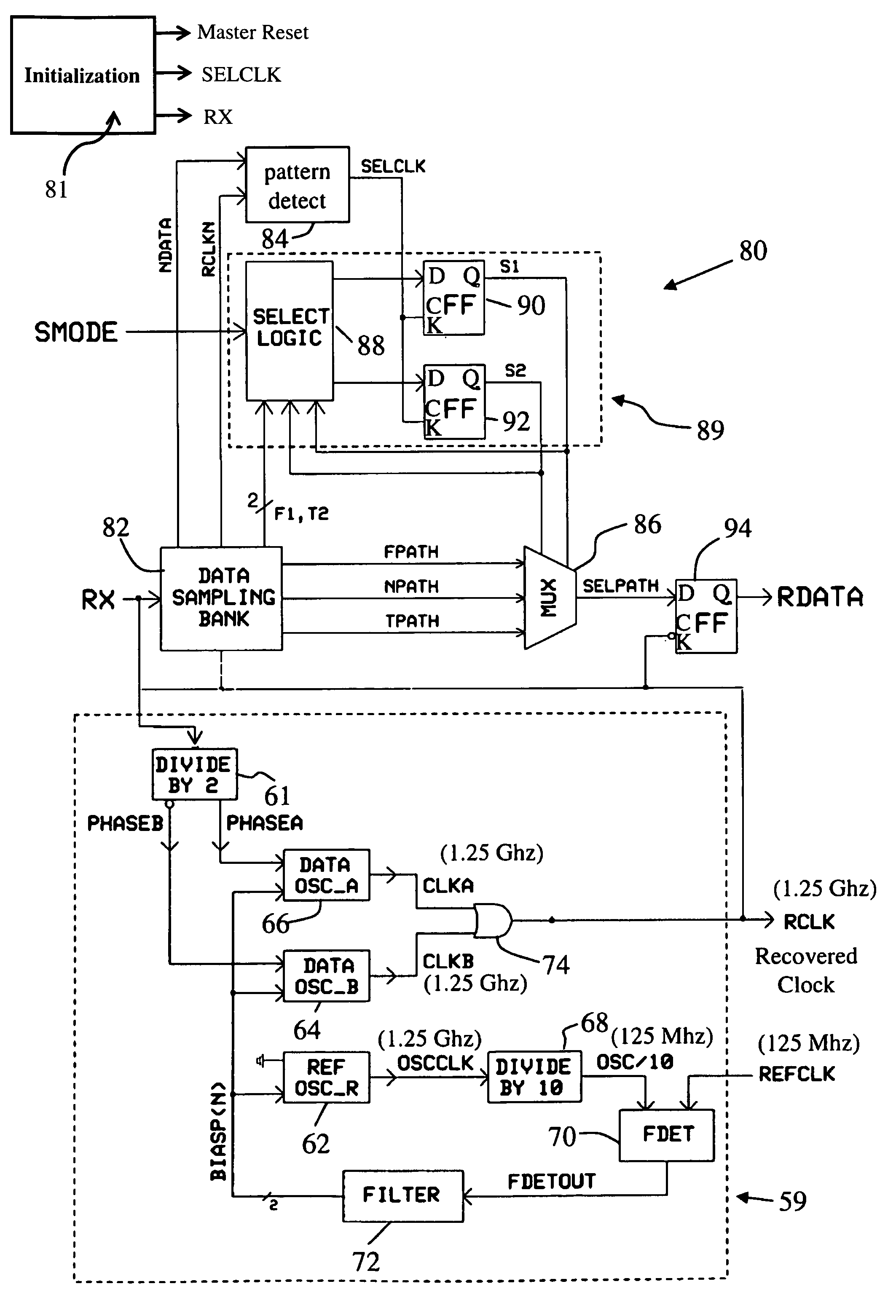
The present invention provides a circuit and method for recovering clock and data signals from a digital input signal in a digital communications system. The circuit can operate at different data rates and can handle burst-mode signals without needing an extended header block that reduces effective bandwidth. The circuit uses a locally generated clock signal and alternative, adaptively selected and updated delay times to accurately reconstruct and retime an incoming data stream in synchrony with the recovered clock. The circuit detects a preselected bit pattern and selects an optimal delay time to accommodate much larger timing jitter in the incoming data without unacceptable bit error rates. The technical effects of the invention include improved data recovery and synchronization with the clock signal, regardless of the data rate or burst-mode signaling used.

Problems solved by technology

NRZ format typically presents a greater difficulty, because fewer transitions are available from which to recover the clock.
The problem of clock recovery is particularly challenging in high-speed, burst mode communications, by which is meant a situation in which a relatively large amount of information is transmitted during a transmission interval, followed by a quiescent interval of indeterminate duration.
The desirability of burst-mode transmission arises in many data communications situations.
While certain known CDR circuits function acceptably well with an extended, if not continuous, data stream, burst-mode transmission presents far greater difficulties.
However, PLL circuits, including that of FIG. 1, ordinarily require a relatively long time to settle before they are properly synchronized.
A further difficulty is that the signals encountered in data communications are not simple sine waves or modulated sine waves, in which there is substantial harmonic content at the base frequency.
Over a long time, each recipient often requires only a small portion of the total available bandwidth, but still desires frequent and data-intensive rapid responses for short, randomly occurring periods.

Method used


Image

  • Data sampling circuit and method for clock and data recovery
  • Data sampling circuit and method for clock and data recovery
  • Data sampling circuit and method for clock and data recovery

Examples


Embodiment Construction

[0031]In one aspect of the invention, there is provided a circuit and method for recovering clock and data signals carried in a digital communications system to a receiving location. The data may be transmitted by either electrical or optical techniques. The circuit operates on a digital input signal in the form of electrical impulses. When the circuit is used in conjunction with an optical system, the propagating light pulses are converted using any converter known in the optical fiber transmission art to provide corresponding electrical impulses. The circuit may be used for continuous data streams, but is particularly useful in connection with burst-mode communications.

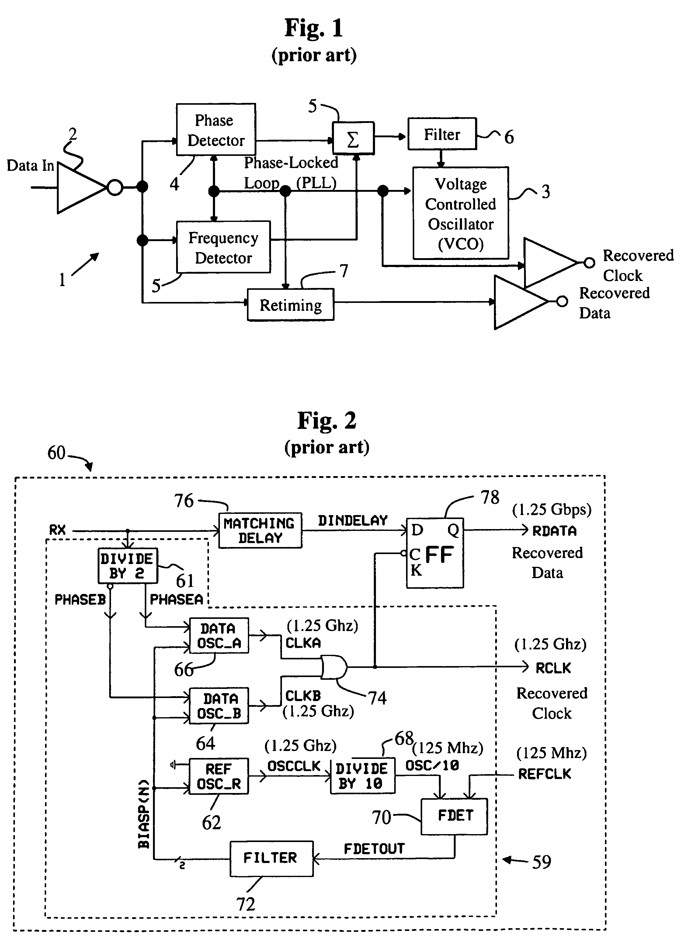
[0032]Referring now to FIG. 2, there is depicted in block diagram form a known CDR circuit 60 usable for burst-mode communications. The circuit 60 acts to accepts an incoming NRZ-formatted digital signal denoted as data RX, from which is obtained a regularized, recovered data stream RDATA and a recovered clock RCLK....


PUM


Abstract

A clock and data recovery circuit and method are used in a digital data communications system. The circuit and method are effectively employed for high speed, burst-mode transmission and allow rapid recovery of the clock and data signals without the need for an extended header, and notwithstanding the presence of substantial timing jitter. The method adaptively selects from among three delay times for the extraction of data by identifying a frequently recurring incoming pattern in the incoming data. The delay time is selected in a manner that insures that the same pattern is present in the reconstructed, resynchronized output data.

Description

BACKGROUND OF THE INVENTION[0001]1. Field of the Invention[0002]The present invention relates to a data communications circuit; and more particularly, to a circuit and method for clock and data recovery in high speed digital communications via optical fiber or wire connection.[0003]2. Description of the Prior Art[0004]Present telecommunications and computer systems require the high data-rate transmission of digital information between different circuits. These circuits may be in close proximity, such as within a single equipment cabinet, or they may be separated by very long distances. Data may be transmitted either by electrical impulses carried using a wired connection such as a coaxial cable or a conductive trace on a circuit board or as light pulses transmitted through optical fibers. Light pulses are generally generated by laser diodes (LD's) or light emitting diodes (LED's) and injected into long fibers of glass or polymeric materials. The fibers are capable of propagating the...

Claims


Application Information

Patent Timeline
Patent Type & Authority Patents(United States)
IPC IPC(8): H04L7/00H04L7/02H04L27/22
CPCH04L7/08H04L7/046
Inventor FISCHER, WILHELM C.INGLIS, DAVID A.OTA, YUSUKE
Owner GOFOTON HLDG
Learn More