Multi-wavelength, bi-directional optical multiplexer

a multi-wavelength, bi-directional technology, applied in multiplex communication, electromagnetic repeaters, instruments, etc., can solve the problems of difficult implementation in practical and cost-effective ways, many customers crave even greater bandwidth, etc., to achieve low cost, high level of skill, and easy and economical implementation

Active Publication Date: 2006-06-13
GOFOTON HLDG
View PDF47 Cites 35 Cited by
  • Summary
  • Abstract
  • Description
  • Claims
  • Application Information

AI Technical Summary

Benefits of technology

[0014]The system is readily and economically implemented. In addition, the system can service users who require the aforementioned data and video feeds either singly or in combination. Advantageously, users who do not need the video feed are furnished a simple, inexpensive multiplexer, which is far less costly than prior-art, three-port multiplexers affording all the capabilities. However, the video feed can be added later if desired by simply adding an additional video module that may be provided with simple connectors, so that a high level of skill is not required for its installation.

Problems solved by technology

While coaxial service provides a much wider bandwidth than ordinary twisted-pair wires, many customers crave even greater bandwidth.
While these protocols provide the services widely demanded by users, their implementation in a practical, cost-effective manner presents significant challenges, most notably the separation of the low and high power signals with adequate immunity to cross-talk.

Method used


Image

  • Multi-wavelength, bi-directional optical multiplexer
  • Multi-wavelength, bi-directional optical multiplexer
  • Multi-wavelength, bi-directional optical multiplexer

Examples


example 1

Testing of an Optical Network Unit

[0035]An ONU-A optical network unit 202 constructed in accordance with the present invention is tested using a system 200 shown schematically in FIG. 5. A video signal is prepared using a video subcarrier generated by a conventional VCR 204 and fed through a wideband amplifier 206. The electrical signal drives a high power laser 208 that provides an analog video optical signal having a power of about 6.5 dBm at a wavelength λ3 of 1.55 μm and an 80% modulation in video fiber 210. A thermoelectrically cooled, distributed feedback laser is used. A data signal is generated using a standard laboratory digital word generator 212 operating at a rate of about 155 Mb / s and connected to a laser light module 214 to produce a digital optical signal at λ2=1.49 μm. The signal is fed through a single mode optical fiber 216 either 10 or 20 km long and then through a conventional 16-way optical splitter 218 and then through a variable optical attenuator 220. The low...

example 2

Testing of an Optical Network Unit with Video Output

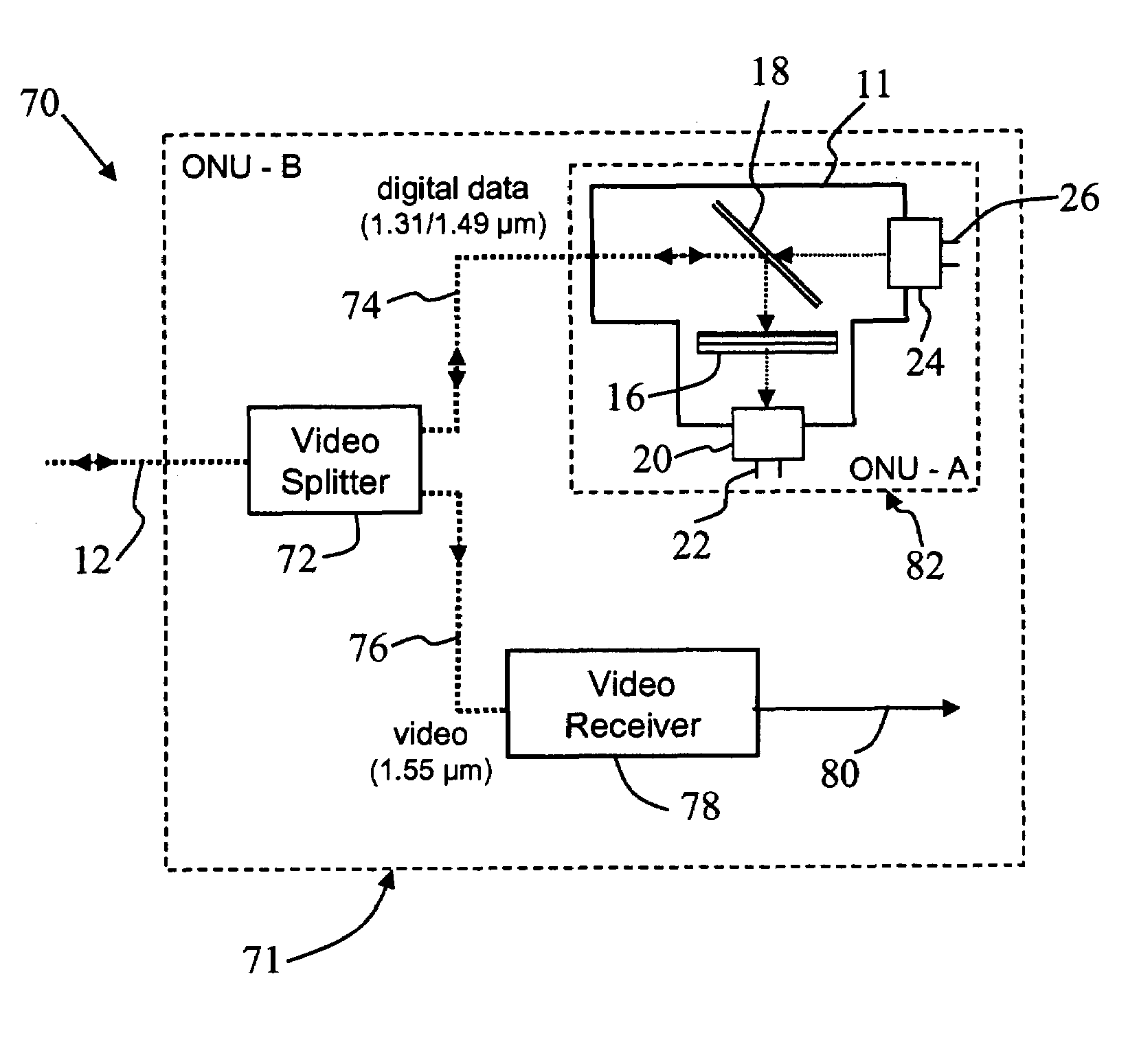
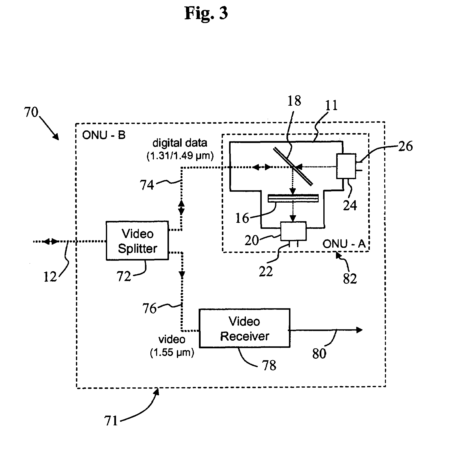
[0036]An ONU-B optical network unit 203 is constructed in accordance with the present invention and then tested using a system 201 shown schematically in FIG. 6. A combined optical signal is prepared using the same system employed in Example 1 and having the characteristics described therein. The combined optical signal is fed to a WDM mirror-based video splitter 72 that directs a portion of the 1.55 μm component through video output fiber 76 to an optical video receiver 78 and a video amplifier 258 connected to a television set 260. The integrity of the video signal is confirmed by observation of the screen image reproduced on the television set. A portion of the incident signal is also routed by the video splitter 72 through data fiber 74 to a bi-directional multiplexer 82 of the ONU-A type. The data output of the multiplexer 82 is connected to a BER counter 228 that demonstrates the integrity of the digital data as evidenced by ...


PUM


Abstract

An optical network unit is associated with a multi-wavelength optical fiber communications system carrying low-power digital signals bidirectionally transmitted at a first and a second wavelength and a high-power analog video signal transmitted at a third wavelength. The unit comprises a housing having a connection for the optical fiber; and an optical filter, first and second optical units, and a beam splitter mounted in the housing. The optical filter is interposed between the fiber termination and the second optical unit, and is adapted to block light of the third wavelength but bidirectionally transmit light of the first and second wavelengths. The system is readily implemented, and any combination of the data and video services may be selected. A high level of skill is not required for changing the combination of services procured.

Description

[0001]This application claims the benefit of Application No.: 60 / 487,079, filed Jul. 15, 2003.BACKGROUND OF THE INVENTION[0002]1. Field of the Invention[0003]The present invention relates to an optical multiplexer; and more particularly, to a multi-wavelength, bi-directional optical multiplexer useful in an optical fiber data transmission system.[0004]2. Description of the Prior Art[0005]Transmission of data by optical fiber waveguides, also called fiber optics or optical fibers, has become ubiquitous in the telecommunications and computer industries. Digital information in an electronic system is converted into a series of pulses of light generated by laser diodes (LD's) or light emitting diodes (LED's), which are injected into long fibers of glass or polymeric materials. The fibers are capable of propagating the light with extremely low losses and acceptably low dispersion, whereby information embodied in the modulation pattern may be conveyed. The light that emerges from the othe...

Claims


Application Information

Patent Timeline
Patent Type & Authority Patents(United States)
IPC IPC(8): H04J14/00G06FH04B10/27H04B10/272H04B10/29H04J14/02
CPCG02B6/4246H04J14/0226H04J14/0252H04J14/0232H04J14/0247H04J14/0282
Inventor OTA, YUSUKECHEN, JIAN-GUANG
Owner GOFOTON HLDG
Why Eureka
Try Eureka