Method for laser cutting tubing using inert gas and a disposable mask

a technology of inert gas and laser cutting tubing, which is applied in the field of hollow workpiece laser cutting tubing, can solve the problems of stents being more susceptible to failure, workpieces being discarded, and weakening of opposite sides, so as to prevent cracking or fracturing of stents, eliminate the need for grit blasting, and eliminate the effect of sidewall oxidation

Inactive Publication Date: 2011-04-26
ABBOTT CARDIOVASCULAR
View PDF28 Cites 28 Cited by
  • Summary
  • Abstract
  • Description
  • Claims
  • Application Information

AI Technical Summary

Benefits of technology

[0013]The present invention is directed to methods for laser cutting a tubular workpiece which helps to reduce the number of post-cutting processing steps by preventing oxidation and preventing recast from adhering to the workpiece material during the laser cutting process. The present invention prevents oxidation of the workpiece by utilizing a laser apparatus that utilizes an inert gas, such as argon or helium, rather than air or oxygen, to create the slots or kerfs which form the pattern cut into the workpiece. The absence of oxygen in the cutting process thus prevents the workpiece from being oxidized during laser cutting. The present invention also utilizes a disposable, sacrificial mask which helps to prevent damage to the workpiece by covering the surface of the workpiece as it is being laser cut. The present invention is particularly beneficial in manufacturing intricately shaped devices from a hollow workpiece, such as a stent.
[0014]In one aspect of the invention, the disposable mask can be placed over at least a portion of the inner surface of the tubular member or tubing which is being laser cut. In the laser cutting process, recast material formed during the cutting process is forced through the kerf via the pressurized inert gas and is collected on the surface of the disposable mask, rather than on the inner surface of the tubular member. Tubing made from Nitinol can be laser cut using an inert gas without the risk of the recast material being welded onto the inner surface of the tubular member. During the cutting operation, both the tubular member and the disposable mask are simultaneously cut to the same pattern. During cutting, the expelled molten Nitinol collects on the inner surface of the disposable mask instead of directly on the inner surface of the tubular member, and afterward the expelled material and sacrificial mask can be removed because neither are strongly affixed to the inner surface of the Nitinol workpiece. Because the inert gas prevents oxidation of the sidewalls of the tubular member, the present invention allows the cut workpiece to be further processed with little or no need to grit blast tough oxidized material from the stent wall prior to electropolishing.
[0016]The present invention utilizes a variety of mechanical techniques to remove the sacrificial mask from the tubular member, along with a variety of chemical removal techniques which can be coupled with the mechanical techniques to quickly and cleanly remove the dross and sacrificial mask from the inner wall of the formed tubular member.
[0017]In one particular aspect of the present invention, the purely mechanical techniques for removing the dross and sacrificial mask is to attack the dross only, utilizing equipment which will grind, hone or bead-blast the dross only. Dross also can be removed utilizing a tool such as a wire brush or reamer. Another way to clean the lased tubular member would be to mechanically attack the sacrificial mask only. Similar mechanical techniques could be used to remove the sacrificial mask. Lastly, these same techniques could be used to mechanically attack both the dross and sacrificial mask. These various techniques provide simple but useful manufacturing steps to separate the lased tubular member from the sacrificial mask and dross.
[0021]In another aspect of the present invention, the procedure for removing the sacrificial mask and dross from the lased tubular member would utilize a combination of chemical removal techniques with mechanical removal techniques, such as the ones addressed above. For example, after cutting, the lased tubular member and sacrificial mask can be subjected to a chemical attack which would only attack the tubular member material therefore dissolving the dross. A chemical solution would be applied to both the tubular member and sacrificial mask. The application of the chemical solution is designed to primarily attack the tubular member, rather than the disposable mask material. As such, the chemicals are selected which preferably attack the material of the tubular member, leaving the sacrificial mask material generally unharmed. In one aspect of the invention, the chemical solution attacks the tubular member by etching it. It should be noted that the recast material (especially the thin connection between the sidewall and recast metal) has a very large surface area to volume ratio and therefore it is much more readily attacked by the chemical solution than the body of the tubular member itself. This process of applying a chemical solution which primarily attacks the material forming the tubular member eliminates or weakens much of the recast material formed in the kerfs and elsewhere, thereby allowing the tubular member and the sacrificial mask material to be more easily separated.
[0028]The use of the present method in forming a medical device, such as a stent, eliminates the need for grit blasting or otherwise chemically removing the oxidized cast material prior to electropolishing since air or oxygen is no longer used in the laser cutting process. The use of the inert gas eliminates the possibility that the sidewalls of the tubular member and recast material will become oxidized during laser cutting. As a result, the elimination of sidewall oxidation helps to prevent cracking or fracturing of the stent during use and eliminates some of the subsequent processing which would be otherwise be needed to remove the oxidized material from the tubular member. As a result, the formed workpiece can be sent for electropolishing without the need for additional processing which could break or irreparably damage the fragile struts which form the stent.

Problems solved by technology

This undesirable burning or partial vaporization of the opposite sidewall is called “burn through” and can result in the weakening of opposite sidewall.
In some cases, burn through may result in the workpiece being discarded.
Oxidation can make a stent more susceptible to failure (e.g., cracking or fracture) during manufacturing or, if not completely removed, in use.
Additionally, recast material can be particularly difficult to remove without damaging the thin struts created by the laser cutting operation.
Therefore, both burn through and formation of recast material presents a formidable problem to the stent manufacturer.
Side walls of the slot or kerf also become oxidized during the cutting process, making the as-cut stent less ductile and thereby more susceptible to cracking or complete fracture during radial expansion or during other subsequent manufacturing steps.
Some methods require the physical removal of the recast material using a reamer or similar equipment and can often damage the thin struts of the stent.
While electropolishing procedures can remove some recast material, often the recast material may be so heavily clad on the surface of the stent that not all of the recast material can be removed by this process.
For example, if the electropolishing procedure is too long in duration, due to accumulated recast material, portions forming the struts of the stent may have too much material removed, resulting in a damaged or generally weakened stent.
However, the presence of this liquid does not always completely block the laser beam, which can allow the inside wall of the tubing to be heated and damaged.
However, laser cutting Nitinol tubing utilizing pressurized argon gas typically cannot directly produce a finished stent because the expelled melted material formed during the cutting process can become “welded” to the inner wall of the tubing.
This welded metallic build up could possibly be removed by later processing including reaming, drilling, electric discharge machining and the like but with difficulty and risk to the integrity of the workpiece.

Method used


Image

  • Method for laser cutting tubing using inert gas and a disposable mask
  • Method for laser cutting tubing using inert gas and a disposable mask
  • Method for laser cutting tubing using inert gas and a disposable mask

Examples


Embodiment Construction

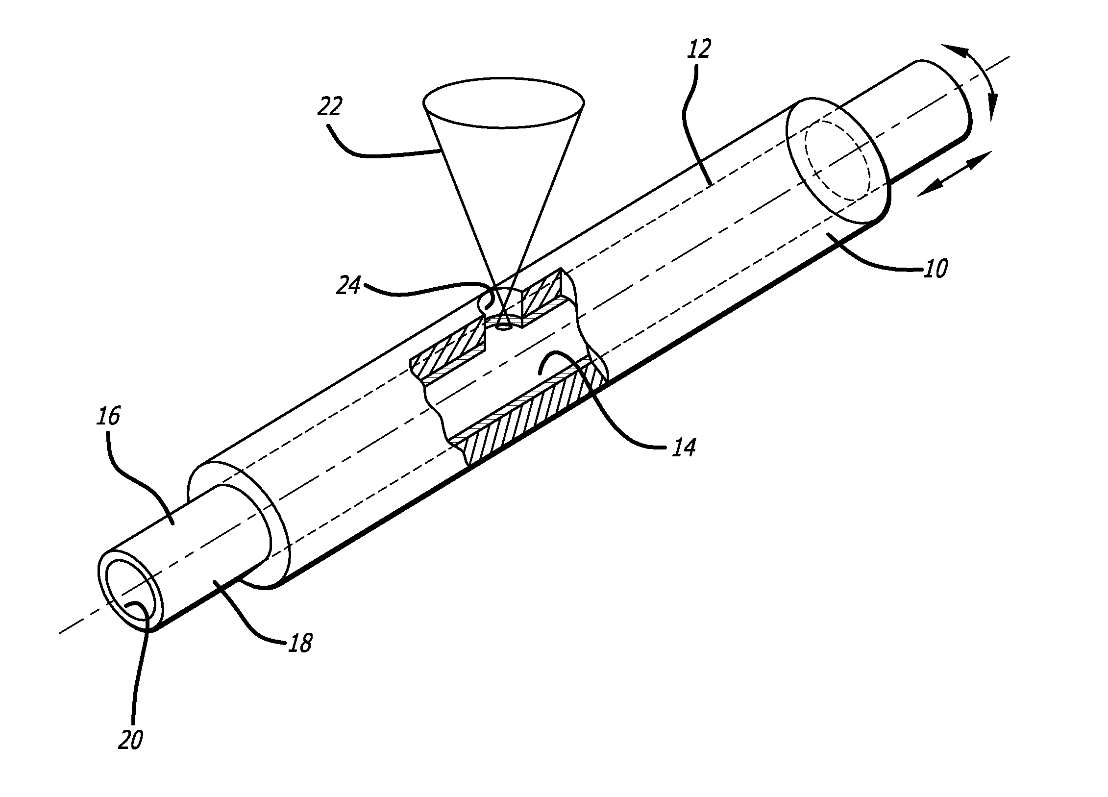
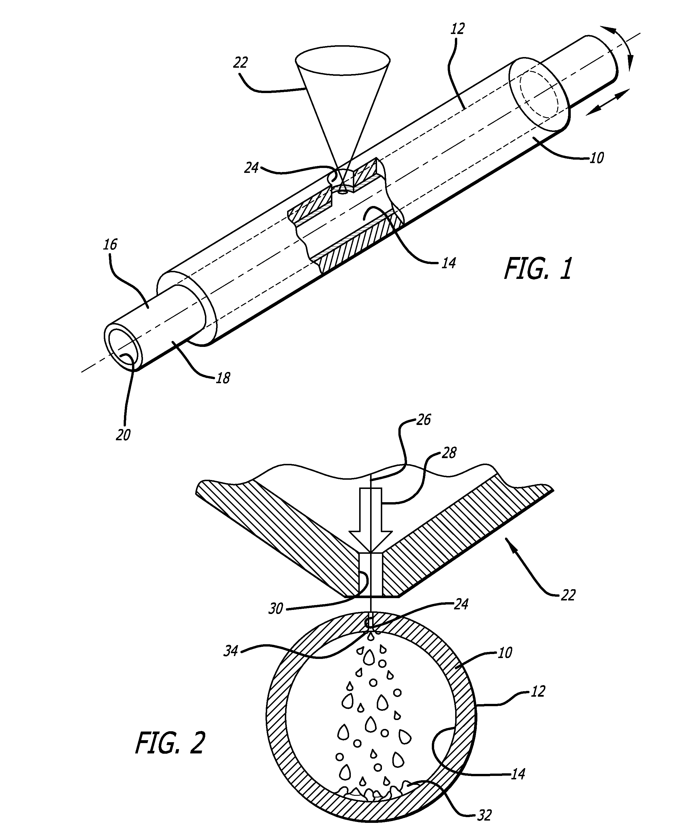
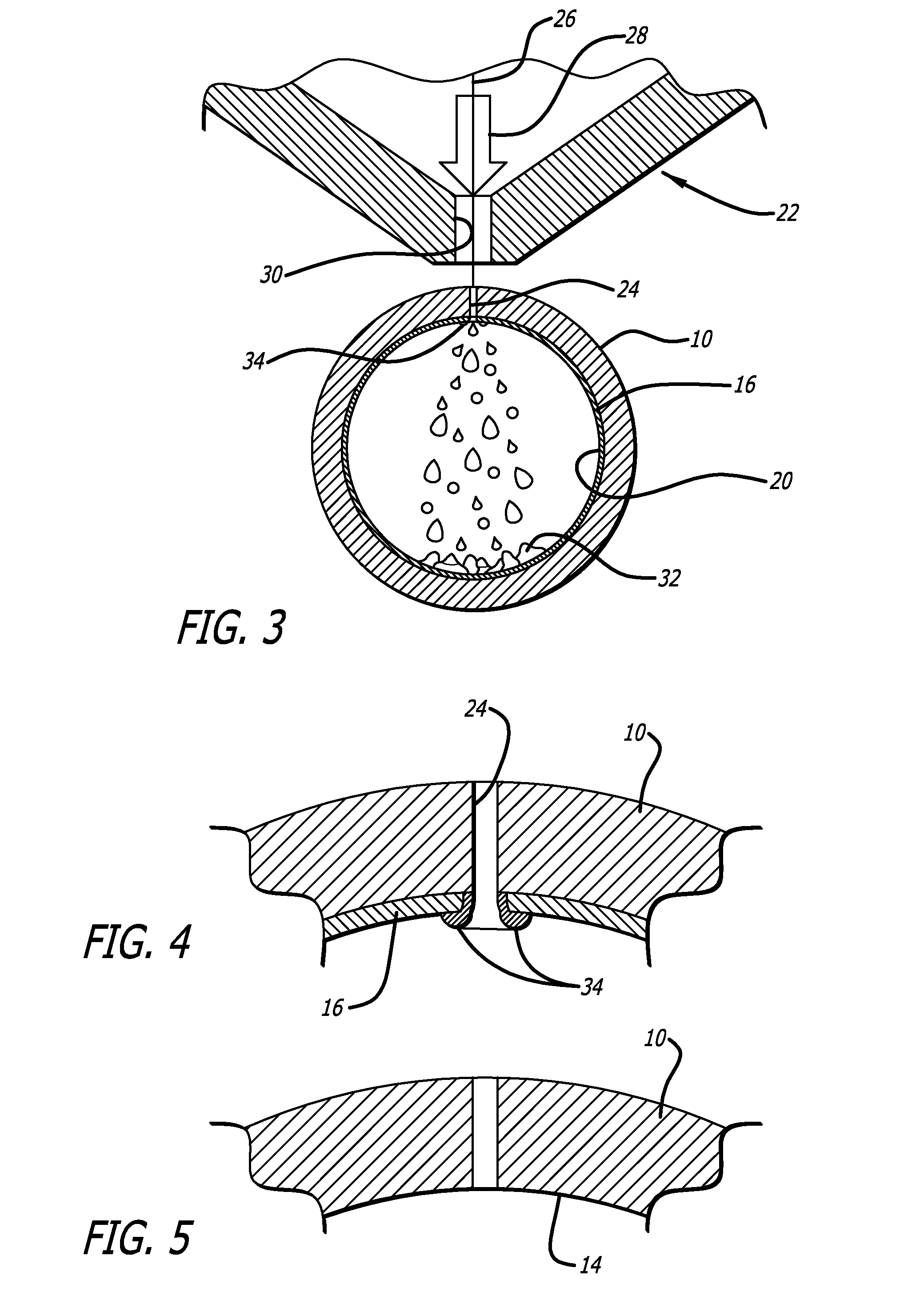
[0035]Referring now to the drawing in which reference numerals represent like or corresponding elements across the drawings, and particularly FIGS. 1 and 3-5, a method of making a device from a hollow tubular member 10 is generally disclosed. The present invention relates generally to methods for laser cutting a length of hollow tubing, or as is it referred to herein a “tubular member,” to form a device, typically a medical device, such as a stent. While most workpieces formed in accordance with the present invention are in the form of a tubular member having a circular cross section, the tubular member could have a non-circular cross section as well. For example, the tubular member could have a rectangular, oval, square, and the like cross section, if desired. Moreover, the invention is not limited to forming stents and has a wide application with respect to other laser cut medical devices and non-medical products, particularly products which require a high precision pattern that i...


PUM

PropertyMeasurementUnit
volume ratioaaaaaaaaaa
time durationaaaaaaaaaa
mechanicalaaaaaaaaaa

Abstract

A method for making a device includes providing a tubular member which will be formed into the device, masking at least a portion of the inner surface of the tubular member with a removable sacrificial material, selectively removing a portion of the tubular member and sacrificial material using a laser device, and mechanically removing the sacrificial material from the inner surface of the tubular member. The method may also include applying a chemical solution to the tubular member and sacrificial material which primarily attacks the either the tubular member or sacrificial material.

Description

BACKGROUND OF THE INVENTION[0001]The present invention relates generally to methods for laser cutting a hollow workpiece, such as a length of tubing. The present invention is more particularly directed to methods for fabricating medical devices, such as, for example, expandable endoprostheses, commonly known as stents, using a sacrificial masking material which helps to prevent damage to the workpiece when cutting the workpiece with a laser apparatus that utilizes an inert gas, instead of air or oxygen, in the cutting process.[0002]Stents are particularly useful in the treatment and repair of blood vessels after a stenosis has been compressed by percutaneous transluminal coronary angioplasty (PTCA), percutaneous transluminal angioplasty (PTA), or removed by atherectomy or other means, to help improve the outcome of the procedure and reduce the possibility of restenosis.[0003]Stents are generally cylindrically shaped devices which function to hold open, and sometimes expand, a segmen...

Claims


Application Information

Patent Timeline
Patent Type & Authority Patents(United States)
IPC IPC(8): B23K26/38
CPCB23K26/16B23K26/38B23K2201/06B23K2101/06
Inventor BIALAS, MICHAELSIMPSON, JOHN A.BARBIER, ROBERT
Owner ABBOTT CARDIOVASCULAR
Why Eureka
Try Eureka