
Semiclosed Brayton cycle power system with direct heat transfer

a technology of heat transfer and cycle power system, which is applied in the direction of hot gas positive displacement engine plants, machines/engines, jet propulsion plants, etc., can solve the problems of system releasing a toxic cloud of lioh into the environment, system failure to heat exchanger and underwater device, and severe stress of oxidant injectors, etc., to achieve the effect of increasing power density

Active Publication Date: 2011-05-10
THE UNITED STATES OF AMERICA AS REPRESENTED BY THE SECRETARY OF THE NAVY
View PDF8 Cites 58 Cited by
  • Summary
  • Abstract
  • Description
  • Claims
  • Application Information

AI Technical Summary

Benefits of technology

[0010]Accordingly, it is a general purpose and object of the present invention to provide an improved Brayton cycle power system. A further object of this invention is that the system be compact and capable of higher power densities than the molten metal versions and have the added advantage of burning a hydrocarbon fuel with oxygen.

Problems solved by technology

The working fluid, water, and the liquid metal fuel, lithium, react chemically with one another; therefore, a leak in the heat transfer tubes causes a violent reaction which generates a significant amount of heat and gas resulting in failure of the heat exchanger and the underwater device.
Furthermore, should a leak occur in a land based system, the system will release a toxic cloud of LiOH into the environment.
Other problems the phase change of the working fluid, severe stress of the oxidant injectors due to high reaction zone temperatures, and slow start up time.
Prior art Brayton cycle systems cannot be used in underwater systems because the components of the Brayton cycle, principally the conventional Brayton heat exchanger, will not fit in the restricted space available in underwater vehicles.
A compact heat exchanger can be made by increasing gas velocity through the heat exchanger to achieve higher heat transfer coefficients; however, this results in greater heat exchanger pressure drop.
In the Brayton cycle, however, compressor power is typically a large part of the gross power (½); therefore, small increases in gas velocity and heater pressure drop reduce the Brayton cycle efficiency below that of the Rankine cycle.

Method used


Image

  • Semiclosed Brayton cycle power system with direct heat transfer
  • Semiclosed Brayton cycle power system with direct heat transfer

Examples


Embodiment Construction

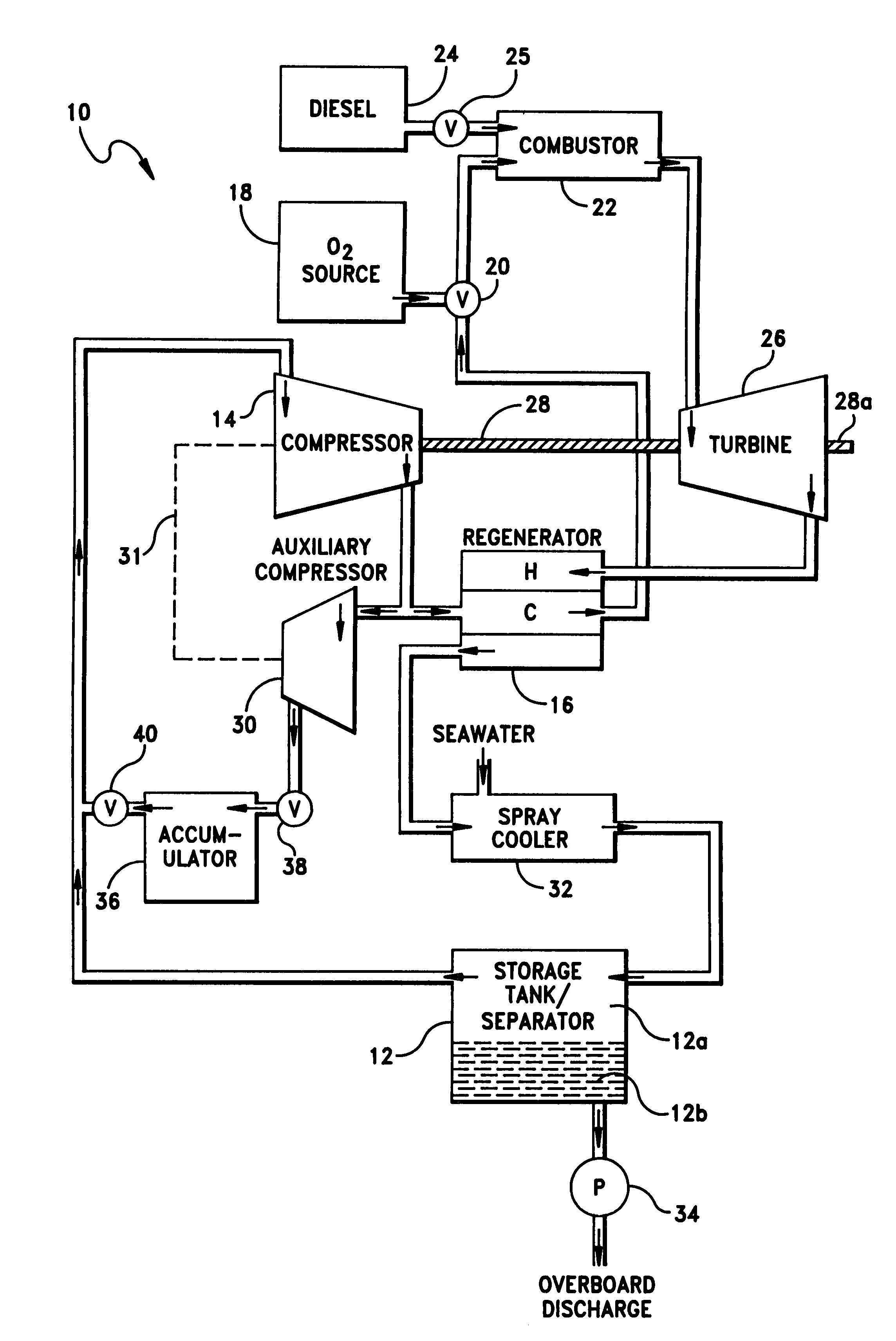
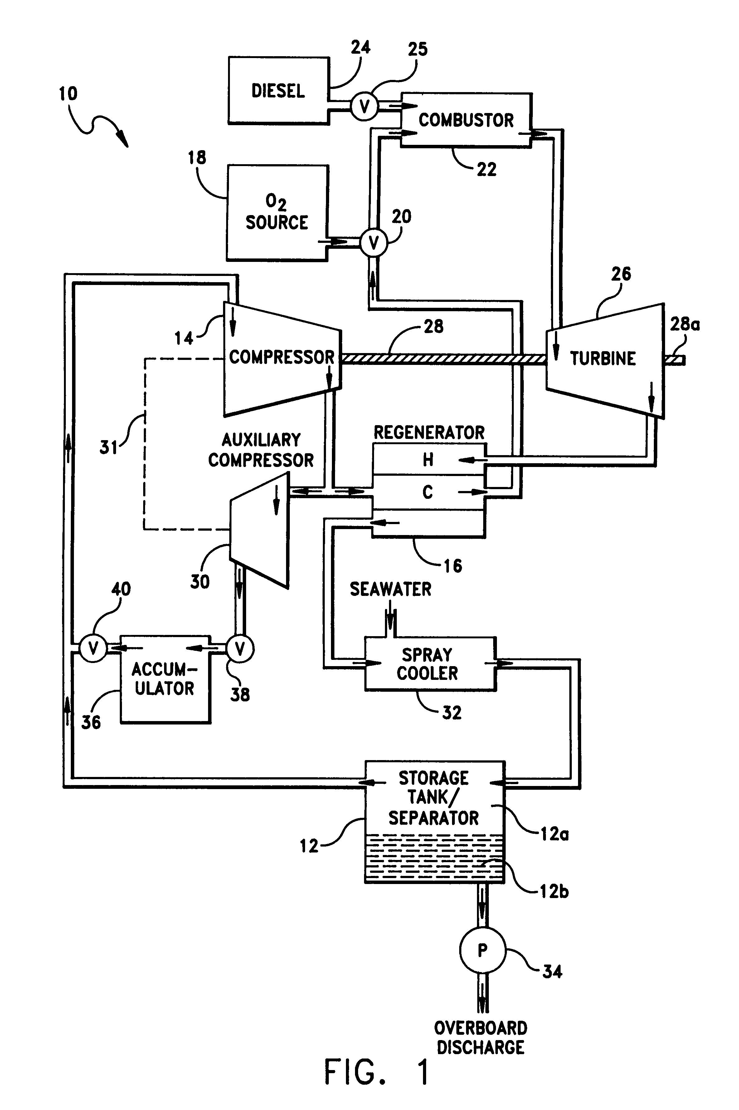
[0014]Referring now to FIG. 1 there is shown a semiclosed Brayton cycle power system 10. System 10 has a storage tank / separator 12 initially containing an inert gas 12a. Preferably, the inert gas is argon; however, the gas can also be a mixture of helium and xenon. The inert gas is compressed in a compressor 14 and transported to a regenerator 16 wherein the gas is partially heated. Upon exit from regenerator 16 the partially heated gas is mixed with oxygen from O2 source 18 by mixing valve 20. The resulting gas mixture is transported to a combustor 22. Diesel fuel from diesel fuel tank 24 is also transported to combustor 22 via diesel fuel control valve 25. Combustion of diesel fuel and oxygen occurs in combustor 22 by conventional means. The diluent inert gas mixed with oxygen acts to reduce the combustion temperature and prevent damage to combustor 22. Combustion results in the formation of a steam, CO2, and hot inert gas working fluid. The steam / CO2 / inert gas working fluid is co...


PUM


Abstract

A semiclosed power system utilizing a Brayton cycle with combustion occurring between diesel fuel and O2 in direct contact with an inert gas. The inert gas and products of combustion form a heated working fluid which is expanded in a turbine to provide power. The expanded working fluid is then used in a regenerator to heat the cooler, compressed inert gas before the inert gas is transferred to the combustor. The expanded working fluid is cooled by direct contact with seawater causing the steam within the expanded working fluid to condense to water and CO2 in the working fluid to be dissolved in the water and seawater. The inert gas is separated from the fluids and recycled within the system. The fluids are pumped overboard.

Description

STATEMENT OF GOVERNMENT INTEREST[0001]The invention described herein may be manufactured and used by or for the Government of the United States of America for governmental purposes without the payment of any royalties thereon or therefor.[0002]This patent application is copending with the related applications by the same inventor filed on the same date as subject patent entitled Closed Cycle Brayton Propulsion System with Direct Heat Transfer, Ser. No. 07 / 926,116, filed 7 Aug. 1992 Closed Brayton Cycle Direct Contact Reactor / Storage Tank with Chemical Scrubber, Ser. No. 07 / 926,090, filed 7 Aug. 1992 Brayton Cycle Direct Contact Reactor / Storage Tank with O2 Afterburner, Ser. No. 07 / 926,200, filed 7 Aug. 1992 Brayton Cycle Power System with Direct Combustion Heat Transfer, Ser. No. 07,926,115, filed 7 Aug. 1992.BACKGROUND OF THE INVENTION[0003](1) Field of the Invention[0004]The present invention relates to a system and a process for providing power using a semiclosed Brayton cycle wi...

Claims


Application Information

Patent Timeline
IPC IPC(8): F02C7/10
CPCF02C7/10F02C3/24
Inventor DUNN, PAUL M.
Owner THE UNITED STATES OF AMERICA AS REPRESENTED BY THE SECRETARY OF THE NAVY
Learn More