Endovascular devices and methods

a technology of endovascular devices and methods, applied in the direction of fluid jet surgical cutters, catheters, veterinary instruments, etc., can solve the problems of cardiac tissue loss or patient death, significant risks to patient health, pain in angina, etc., and achieve the effect of reducing the chance of vessel perforation

Active Publication Date: 2011-05-10
BOSTON SCI SCIMED INC
View PDF196 Cites 121 Cited by
  • Summary
  • Abstract
  • Description
  • Claims
  • Application Information

AI Technical Summary

Benefits of technology

[0006]In an aspect of the disclosure, a subintimal device may be used to guide conventional devices (for example guide wires, stents, lasers, ultrasonic energy, mechanical dissection, or atherectomy) within the vessel lumen. Additionally, a subintimal device may be used to delaminate vessel wall layers and also may be used to remove tissue from the occlusive lesion or surrounding vessel wall. In one example, the positioning of a subintimal device or the establishment of a delamination plane between intima and medial layers is achieved through the use of a mechanical device that has the ability to infuse a fluid (for example saline). Fluid infusion may serve to apply a hydraulic pressure to the tissues and aid in layer delamination and may also serve to protect the vessel wall from the tip of the subintimal device and reduce the chance of vessel perforation. The infusion of fluid may be controlled by pressure or by volume.

Problems solved by technology

Due to age, high cholesterol and other contributing factors, a large percentage of the population has arterial atherosclerosis that totally occludes portions of the patient's vasculature and presents significant risks to patient health.
For example, in the case of a total occlusion of a coronary artery, the result may be painful angina, loss of cardiac tissue or patient death.
In another example, complete occlusion of the femoral and / or popliteal arteries in the leg may result in limb threatening ischemia and limb amputation.
Commonly known endovascular devices and techniques are either inefficient (time consuming procedure), have a high risk of perforating a vessel (poor safety) or fail to cross the occlusion (poor efficacy).
Physicians currently have difficulty visualizing the native vessel lumen, can not accurately direct endovascular devices toward visualized lumen, or fail to advance devices through the lesion.

Method used


Image

  • Endovascular devices and methods
  • Endovascular devices and methods
  • Endovascular devices and methods

Examples


Embodiment Construction

[0024]The following detailed description should be read with reference to the drawings in which similar elements in different drawings are numbered the same. The drawings, which are not necessarily to scale, depict illustrative embodiments and are not intended to limit the scope of the invention.

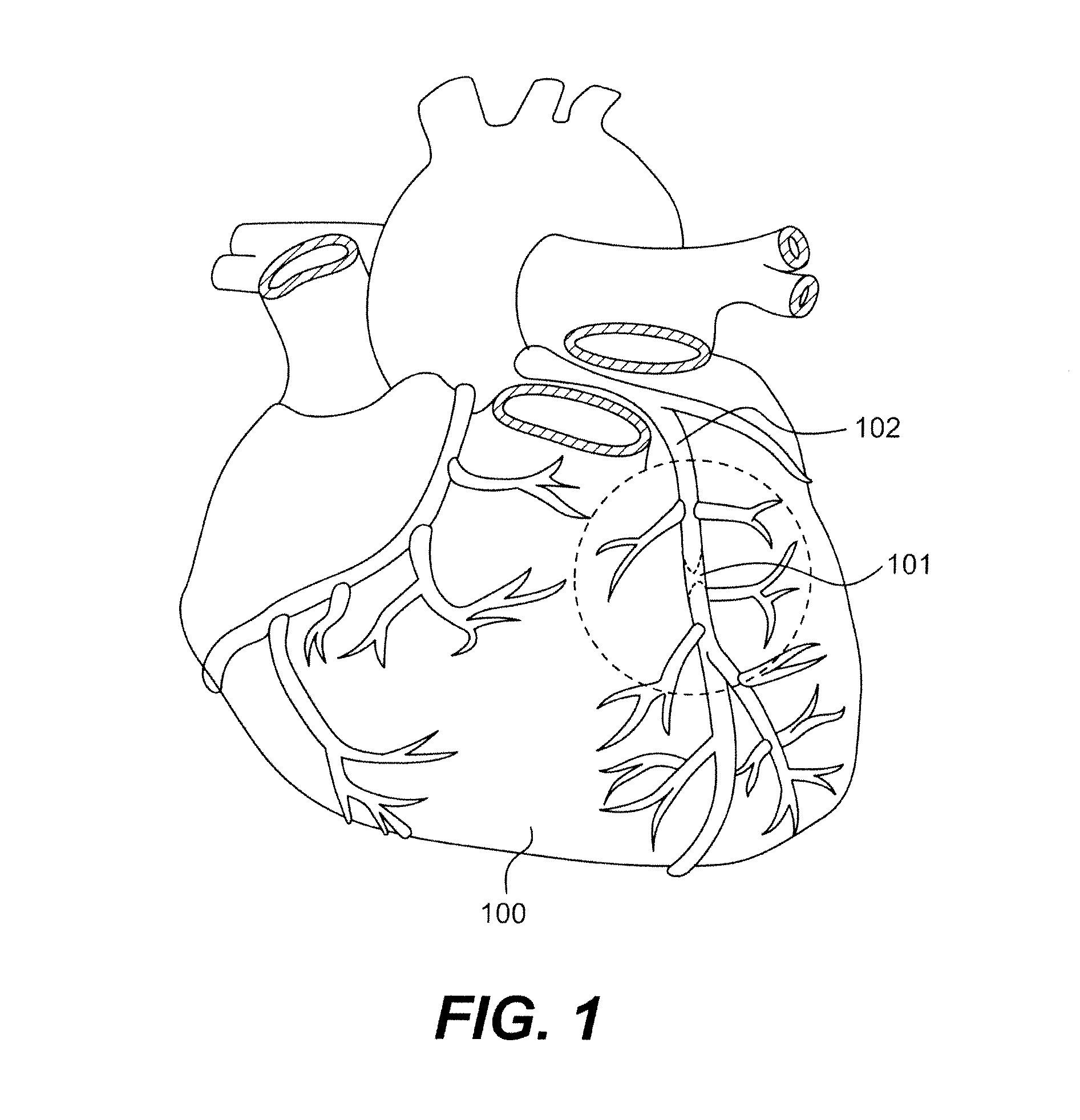
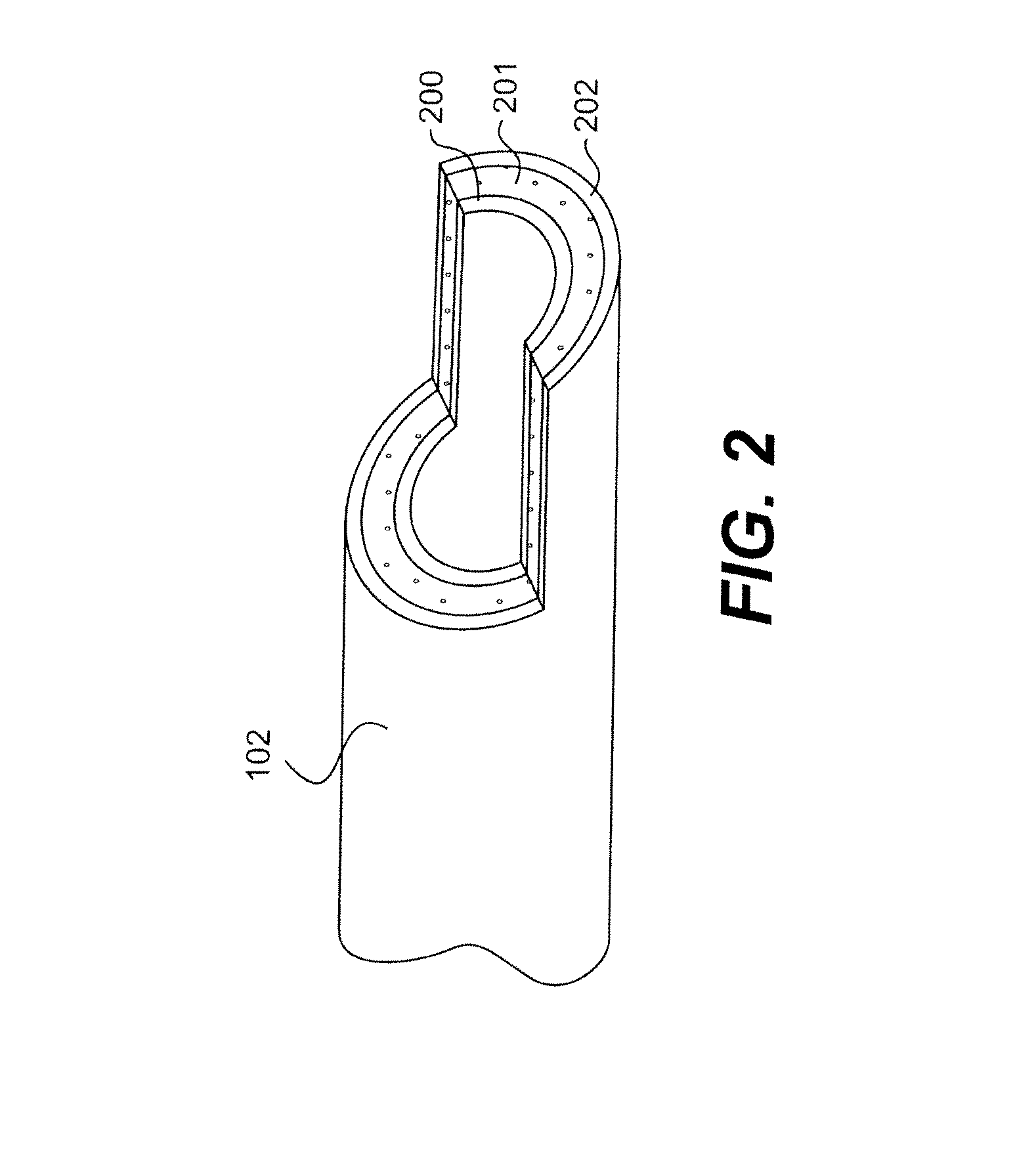
[0025]Referring to FIG. 1, a diseased heart 100 includes a chronic total occlusion 101 of a coronary artery 102. FIG. 2 shows coronary artery 102 with intimal layer 200 (for sake of clarity, the multi layer intima is shown as a single homogenous layer). Concentrically outward of the intima is the medial layer 201 (which also is comprised of more than one layer but is shown as a single layer). The transition between the external most portion of the intima and the internal most portion of the media is referred to as the subintimal space. The outermost layer of the artery is the adventitia 202.

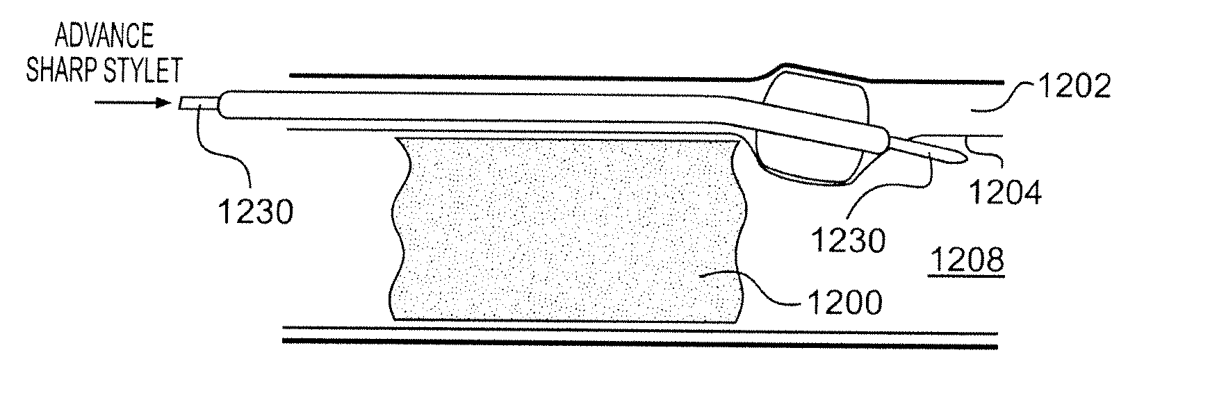
[0026]In an aspect of the disclosure, a subintimal device may be used to guide conventional devices (f...


PUM


Abstract

Devices and methods for the treatment of chronic total occlusions are provided. One disclosed embodiment comprises a method of facilitating treatment via a vascular wall defining a vascular lumen containing an occlusion therein. The method includes providing an intravascular device having a distal portion with a side port, inserting the device into the vascular lumen, positioning the distal portion in the vascular wall, directing the distal portion within the vascular wall such that the distal portion moves at least partially laterally, and directing the side port towards the vascular lumen.

Description

CROSS REFERENCE TO RELATED APPLICATIONS[0001]This application claims the benefit of U.S. Provisional Application No. 60 / 716,287, filed Sep. 12, 2005, under 35 U.S.C. §119(e). In addition, this application also claims the benefit of U.S. Provisional Application No. 60 / 717,726, filed Sep. 15, 2005, under 35 U.S.C. § 119(e). In addition, the application also claims the benefit of U.S. Provisional Application No. 60 / 727,819, filed Oct. 18, 2005, under 35 U.S.C. §119(e). The entire disclosure of each of the above-referenced applications is incorporated by reference herein.FIELD OF THE INVENTION[0002]The inventions described herein relate to devices and associated methods for the treatment of chronic total occlusions. More particularly, the inventions described herein relate to devices and methods for crossing chronic total occlusions and subsequently performing balloon angioplasty, stenting, atherectomy, or other endovascular methods for opening occluded blood vessels.BACKGROUND OF THE ...

Claims


Application Information

Patent Timeline
Patent Type & Authority Patents(United States)
IPC IPC(8): A61M31/00A61B17/22A61M29/00A61M5/32A61F2/958
CPCA61B17/22A61B17/221A61B17/32037A61F2/88A61M29/02A61B17/22031A61B17/00008A61B2017/00252A61B2017/22034A61B2017/22077A61B2017/22094A61B2017/22095A61B2017/320741A61M25/0026A61M2025/006A61M25/104A61M25/0194A61B2017/320056A61B2017/320064A61B2017/320733
Inventor KUGLER, CHAD J.ATKINSON, ROBERT E.
Owner BOSTON SCI SCIMED INC
Why Eureka
Try Eureka