System and method for managing water content in a fluid

a technology of water content and management system, applied in the direction of combustion air/fuel air treatment, machine/engine, combustion gas purification/modification, etc., can solve the problems of inefficiency of conventional water management system, inability or difficult to remove water using condensation system, and inability to achieve the effect of maintaining water quality

Active Publication Date: 2011-05-17
DUCOOL
View PDF83 Cites 36 Cited by
  • Summary
  • Abstract
  • Description
  • Claims
  • Application Information

AI Technical Summary

Benefits of technology

[0017]Embodiments of the invention also provide a system and method for managing water content in a fluid in which cooled desiccant is diluted as it removes water from an airflow, and is collected in a sump of a collection chamber. Diluted desiccant is transferred to a regeneration chamber, where it is heated and brought into contact with another airflow. This effects removal of the water from the desiccant, and the now concentrated desiccant is collected in a sump of the regeneration chamber. The desiccant in the sumps is mixed in such a way as to efficiently control the transfer of heat and mass of the water in the desiccant pools.
[0018]In one embodiment, the two sumps are connected by an aperture, such as an orifice. When the liquid desiccant is sprayed in the collection chamber, its mass and volume increase as it removes water from the air. As the desiccant continues to pickup more water from the airflow, its level in the collection sump rises. When it exceeds the level of the orifice, some of the diluted desiccant enters the regeneration chamber and mixes with the more concentrated desiccant in the regeneration sump; this causes the level of the desiccant in the regeneration sump to rise. When the desiccant in the regeneration chamber reaches a predetermined level, a float-actuated valve opens to allow some of the desiccant to be pumped back into the collection chamber. In this way, mass is not transferred from the collection chamber to the regeneration chamber until the desiccant level in the collection chamber reaches the orifice. Similarly, mass is not transferred from the regeneration chamber to the collection chamber until the desiccant level in the collection chamber moves the float to actuate the valve. The orifice and the float switch can be positioned as desired, such that the mass flow is efficiently controlled.
[0019]Because the temperatures of the desiccant in the two sumps is likely to be different—the desiccant in the collection sump being cooler than the desiccant in the regeneration sump—the invention also controls the heat transfer between the two desiccant chambers. In one embodiment, the warmer, concentrated desiccant from the regeneration sump is passed through a heat exchanger—e.g., an evaporator of a refrigeration system—before it enters the collection chamber. This cools the concentrated desiccant, and may reduce the required energy input into the system, since the desiccant in the collection chamber will not require as much cooling prior to its being sprayed on the airflow in the collection chamber.
[0021]To effect efficient transfer of heat between the two chambers, a system heat exchanger may be used. The system heat exchanger can be configured to receive both streams of desiccant as they are transferred from one chamber to another. Specifically, the cooler, diluted desiccant leaves the collection sump when it reaches the level of the orifice. It then flows through the system heat exchanger and into the regeneration chamber. On the other side, warmer, concentrated desiccant is pumped through the system heat exchanger when the level in the regeneration sump is high enough to actuate the float valve. In the system heat exchanger, the desiccant being pumped to the collection chamber gives up heat, while the desiccant flowing into the regeneration chamber picks up heat. In this way, less cooling is required of the collection chamber desiccant, and less heating is required of the regeneration chamber desiccant. Thus, the heat transfer and the mass transfer are both controlled to provide an efficient system.

Problems solved by technology

Regardless of the reason for managing the amount of water in the air, there are times when conventional water management systems have undesirable limitations.
For example, when the dew point of the air is low, particularly when it is below the freezing point of water, it may be difficult or impossible to remove the water using a condensation system.
Conventional systems of this type are generally inefficient in at least one of the two types of transfer—i.e., heat or mass transfer—because the transfer of one inherently transfers the other, which may be undesirable.
At the same time, however, a large amount of heat may be added by the phase change occurring as the water condenses out of the air; this causes an increase in the enthalpy of the air.
One limitation of the Peterson et al. system is limited control over the amount of desiccant transferred between the sumps.
Specifically, such a system may result in undesirably large quantities of desiccant being pumped between the two sumps in order to continuously regenerate the desiccant.
Because the temperature of the desiccant in the condenser sump may be significantly higher than the temperature of the desiccant in the evaporator sump, an undesirable amount of heat transfer can occur as the large mass of liquid is transferred between the sumps.
This can be very inefficient.
Although this may reduce some of the inefficiency, the process may yet be undesirably inefficient because of the large quantity of liquid being transferred.

Method used


Image

  • System and method for managing water content in a fluid
  • System and method for managing water content in a fluid
  • System and method for managing water content in a fluid

Examples


Embodiment Construction

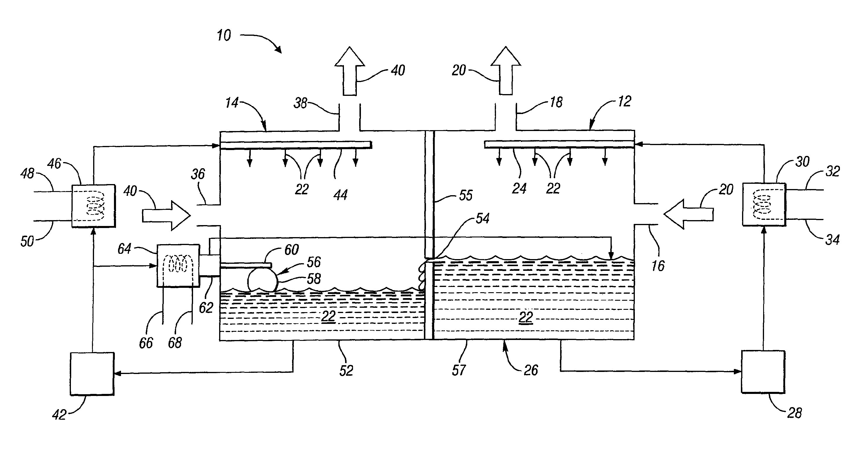
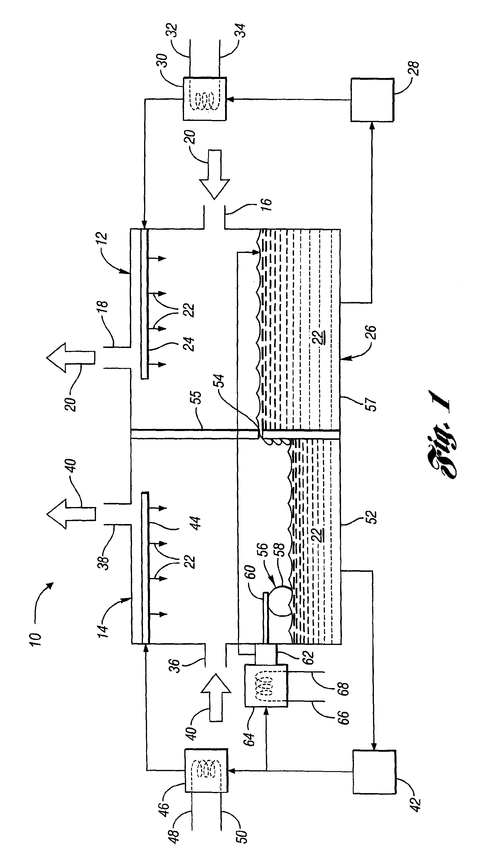
[0026]FIG. 1 shows a system 10 for managing water content in a fluid in accordance with one embodiment of the present invention. In particular, the system 10 is configured to manage the water content in air—either to collect water from the air for storage and subsequent use, or to control the humidity of the air. It is worth noting that although the examples presented herein utilize ambient air as the fluid whose water content is being managed, the present invention is capable of managing the water content of other fluids as well. The system 10 includes a first chamber, or collection chamber 12, and a second chamber, or regeneration chamber 14. The collection chamber 12 includes an inlet 16 and an outlet 18 which allow a first airflow 20 to flow through the collection chamber 12. As the air flows through the collection chamber 12, it contacts a desiccant 22, which, in the embodiment shown in FIG. 1, is sprayed into the chamber 12 via a conduit 24.

[0027]As the air moves through the c...


PUM

PropertyMeasurementUnit
heightaaaaaaaaaa
widthaaaaaaaaaa
water contentaaaaaaaaaa

Abstract

A system and method for managing water content in a fluid include a collection chamber for collecting water from the fluid with a desiccant, and a regeneration chamber for collecting water from the desiccant and transferring it to a second fluid. An evaporator cools the desiccant entering the collection chamber, and a condenser heats the desiccant entering the regeneration chamber. Diluted desiccant from the collection chamber is exchanged with concentrated desiccant from the regeneration chamber in such a way as to efficiently control the transfer of both mass and heat between the chambers. In one embodiment, mass is not exchanged until one or both of the desiccant levels in the chambers exceeds a predetermined level. Heat is transferred between the two desiccant flows as they are transferred between the chambers. This increases efficiency and reduces the energy input required for the evaporator and the condenser.

Description

CROSS-REFERENCE TO RELATED APPLICATIONS[0001]This application is the national stage of International Application No. PCT / IB07 / 04333 filed on Aug. 27, 2007.[0002]This application claims the benefit of U.S. provisional application Ser. No. 60 / 840,312 filed 25 Aug. 2006, which is hereby incorporated herein by reference.BACKGROUND OF THE INVENTION[0003]1. Field of the Invention[0004]The present invention relates to a system and method for managing water content in a fluid.[0005]2. Background Art[0006]Conventionally, water is collected from air, or other gaseous fluids, using condensation systems. An exemplary condensation system provides a surface cooled to a temperature that is at or below the dew point of incoming air. As is well known in the art, the cooling of air at or below its dew point causes the condensation of water vapor from the air and a decrease in the absolute humidity of the air. The humidity of a volume of air is substantially determinative of the amount of water that c...

Claims


Application Information

Patent Timeline
Patent Type & Authority Patents(United States)
IPC IPC(8): B01F3/04
CPCF24F3/1417F24F2003/1458F24F5/00F24F3/14
Inventor FORKOSH, DAN
Owner DUCOOL
Why Eureka
Try Eureka