Apparatus and process for the pyrolysis of agricultural biomass

a technology of agricultural biomass and apparatus, applied in the field of agricultural biomass pyrolysis, can solve the problems of unsuitable mobile implementation of the process, uneconomical prohibitive cost of transporting bulky materials to a central processing site, and difficult collection and transportation economics, so as to prevent segregation, prevent the escape of materials, and accelerate the heat transfer of biomass

Inactive Publication Date: 2011-05-17
AGRI THERM
View PDF14 Cites 71 Cited by
  • Summary
  • Abstract
  • Description
  • Claims
  • Application Information

AI Technical Summary

Benefits of technology

[0014]The combustion chamber may have a common surface with the pyrolysis reactor. The combustion chamber may be cylindrical and the pyrolysis reactor may be located within an annular space about the combustion chamber. In this case, the common surface may then be an annular wall located between the pyrolysis reactor and the combustion chamber. The pyrolysis reactor may be divided into one or more chambers within the annular space and / or may contain one or more baffles to promote mixing or to help direct either biomass or the inert fluidizable media in a desired direction. The bottom of the pyrolysis reactor may comprise a fluid distributor. The fluid distributor may comprise a plate having a plurality of holes and may include means to prevent plugging of the holes by the fluidizable media, the biomass, char, or a combination thereof. The plate may be flat or may be frustoconical in shape in order that the material in the pyrolysis reactor moves inwardly and downwardly toward the lift tube inlet(s).
[0021]The apparatus of the present invention is particularly well suited to the pyrolysis of low density agricultural biomass (eg: biomass having a density less than that of the first inert fluidizable media). The low density agricultural biomass may comprise straw, stalks, husks, chaff, bark, wood chips, etc. and may comprise a waste product from agriculture or other industries. The introduction of the fluidizable media into the freeboard area of the fluidized bed helps prevent light materials from escaping the bed. The downward circulation of the fluidizable media though the bed also entrains the biomass and advantageously prevents segregation. The introduction of the biomass within the bed is useful in preventing the escape of materials and in causing rapid heat transfer to the biomass.
[0022]The apparatus of the present invention is compact and may be readily mounted on a trailer or other mobile vehicle for transportation to various farm locations. This advantageously obviates the need for transporting the biomass over large distances, which dramatically reduces the overall cost of the process. A condensable gaseous product may be produced during the pyrolysis process that has significant economic value when recovered. The condensable gaseous product may comprise a fuel oil product or other complex hydrocarbon oils. The condensable gaseous product can represent a valuable income stream for farmers, particularly in the developing world.

Problems solved by technology

Low density agricultural biomass (eg: straw, stalks, husks, chaff, bark, wood chips, etc.) is typically widely dispersed within a given geographical area, difficult to collect and expensive to transport economically.
In the fast pyrolysis of low density agricultural biomass, a common problem that makes the process uneconomical is the prohibitive cost of transporting these bulky materials to a central processing site.
The process takes place at low temperature and employs long residence times. This process is therefore not suitable for mobile implementation.
The reactor does not contain any fluidizable media and no fluidized bed is employed, which limits heat and mass transfer within the reactor.
Although this configuration leads to rapid mass transfer, it requires careful control of particle size, is complicated to operate and is not well-suited to mobile implementation due to its size and energy requirements.
This reactor does not employ lift tubes but rather circulates the entire bed between the combustion chamber and pyrolysis reactor; as a result, there is both fluid and solid communication between the zones, which makes it difficult to precisely control process conditions and achieve the desired product characteristics.
To date, conventional fast pyrolysis processes employ multiple vessels, are complex to operate, are inflexible and / or are not suitable for mobile operation.
Compact systems that combine the combustion chamber and pyrolysis reactor in a single vessel usually involve mixing of fluids and / or solids between the two portions of the vessel; this leads to contamination and / or destruction of the most valuable condensable liquid products in the product gas.

Method used


Image

  • Apparatus and process for the pyrolysis of agricultural biomass
  • Apparatus and process for the pyrolysis of agricultural biomass
  • Apparatus and process for the pyrolysis of agricultural biomass

Examples


Embodiment Construction

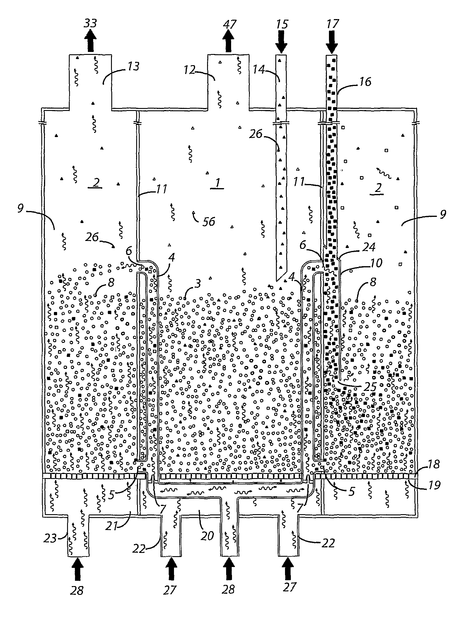
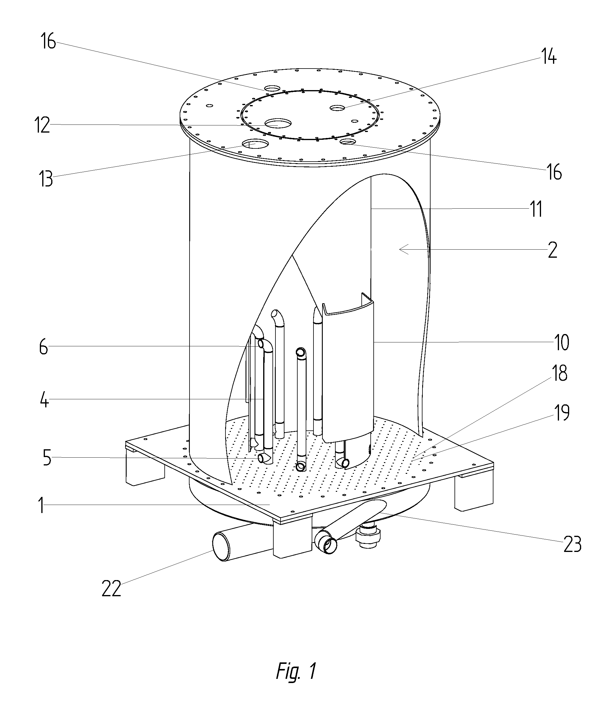
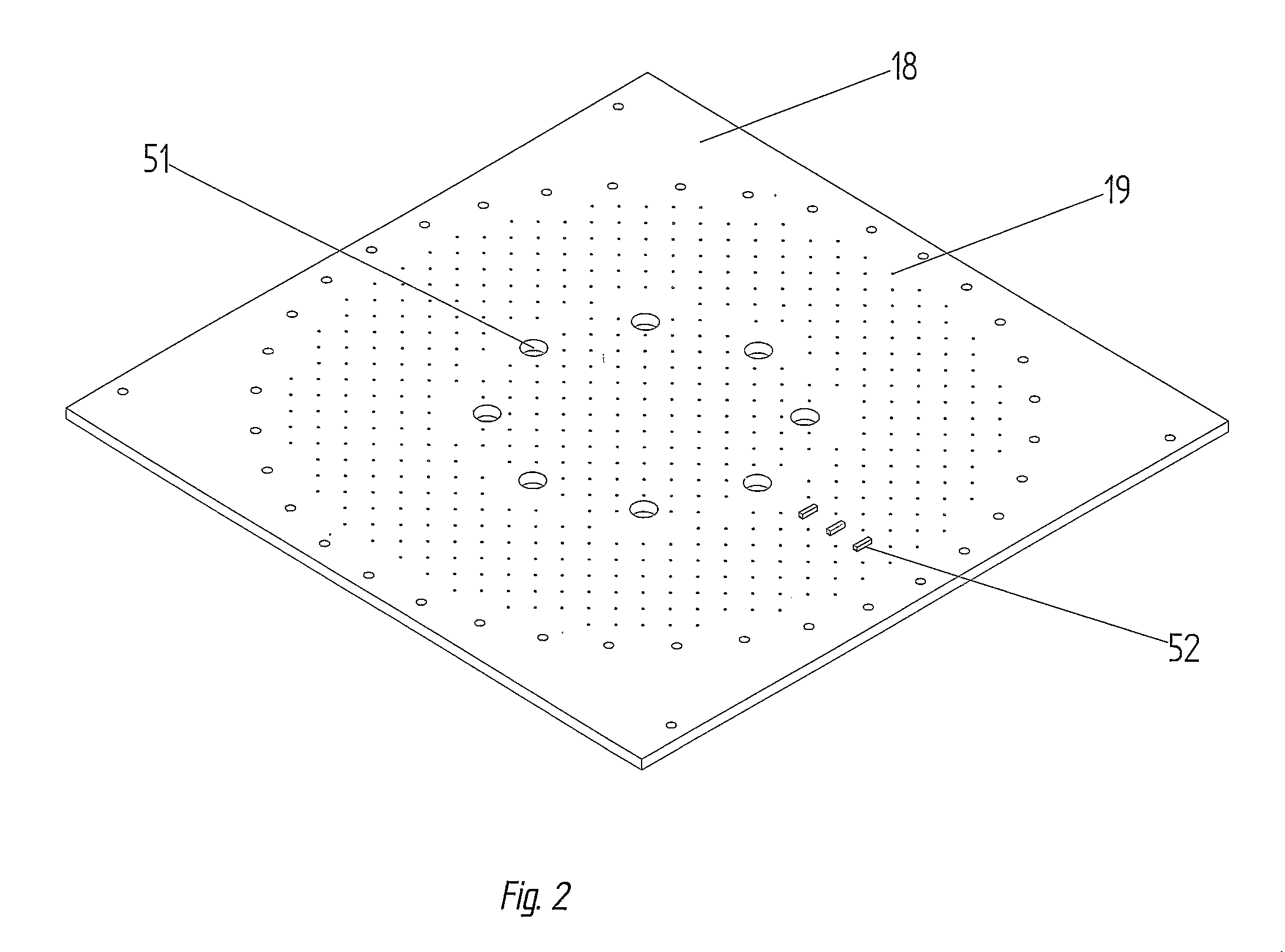
[0029]Referring to FIGS. 1-3, an embodiment of an apparatus according to the present invention comprises a central combustion chamber 1 surrounded by an annular fluidized bed pyrolysis reactor 2. The combustion chamber 1 preferably comprises a fluidized bed and is designed to accommodate a second inert fluidizable media 3. A plurality of lift tubes 4 are provided within the combustion chamber 1, each having a lower inlet 5 and an upper outlet 6 located in the pyrolysis reactor 2. Each lift tube 4 includes a nozzle 7 proximal the inlet 5 for educting a first inert fluidizable media 8 located within the pyrolysis reactor 2 upwardly through the lift tube 4. The outlet 6 of each tube 4 is located within a freeboard area 9 of the reactor 2 when the fluidized bed is in operation. A pair of directional devices, each comprising a vertical duct 10, is provided within the pyrolysis reactor 2 on the common wall 11 shared with the combustion chamber 1. Other embodiments of directional devices (...


PUM

PropertyMeasurementUnit
temperatureaaaaaaaaaa

Abstract

An integrated combustion chamber and fluidized bed pyrolysis reactor. In one embodiment, the combustion chamber is cylindrical and the pyrolysis reactor is provided annularly about the combustion chamber with an annular wall that provides a common surface for heat transfer. A lift tube in fluid communication with the pyrolysis reactor is provided within the combustion chamber for circulating biomass and an inert fluidizable media upwardly through the lift tube; this advantageously increases heat transfer and leads to more rapid pyrolysis. The media and biomass exit the lift tube into either a freeboard area of the pyrolysis reactor or into a low density region of the fluidized bed. A condensable gaseous product is produced during pyrolysis that has economic value. The apparatus and process are especially well suited to the pyrolysis of low density agricultural biomass. The apparatus is compact and particularly well suited to mobile operation.

Description

CROSS-REFERENCE TO RELATED APPLICATIONS[0001]This application is a national entry under 35 U.S.C. 371 of PCT / CA2006 / 000933, filed Jun. 7, 2006, that claims the benefit of U.S. patent application 60 / 688,338, filed Jun. 8, 2005, which is incorporated herein by reference.FIELD OF THE INVENTION[0002]The invention relates to the pyrolysis of agricultural biomass. More particularly, the invention relates to an integrated combustion chamber and fluidized bed pyrolysis reactor that is compact and particularly well suited to mobile operation. A lift tube in fluid communication with the pyrolysis reactor is located within the combustion chamber for circulating biomass and an inert fluidizable media upwardly therethrough; this advantageously increases heat transfer and leads to more rapid pyrolysis. The apparatus and process are especially well suited to the pyrolysis of low density agricultural biomass.BACKGROUND[0003]Fast pyrolysis is a high temperature process (350 to 800° C.) in which a bi...

Claims


Application Information

Patent Timeline
Patent Type & Authority Patents(United States)
IPC IPC(8): C10B51/00
CPCC10B47/24C10B49/22C10B53/02F23G5/0276F23G5/30F23G7/10F23C10/26C02F11/10Y02E50/14F23G2203/503Y02E50/10
Inventor BERRUTI, FRANCOBRIENS, CEDRICGOLDEN, RONALD
Owner AGRI THERM
Why Eureka
Try Eureka