[0011]The inventors have found that, during the transition from the dynamically
stable state to the dynamically unstable state, surprisingly droplets with constant droplet diameters are formed which form the dispersed phase of the emulsion. The emulsion formed in the dispersion region is monodisperse. While the liquid which is transformed into the dispersed phase experiences a certain
Laplace pressure in the channel upstream of the dispersion region due to the interaction with the bottom and top surfaces of the channel, the
Laplace pressure is reduced in the dispersion region and therefore the
layer thickness of the flow increases and a local suction effect is produced in the direction of the liquid flow. Since, as a result of this suction effect at the cross-sectional widening of the channel (dispersion region), the liquid is drawn out of the channel more rapidly than it can flow in, it is pinched off and therefore the droplet shape of the dispersed phase is formed. It has been found that this effect of reducing the
Laplace pressure and forming droplets is carried out periodically with a high degree of regularity, so that the dispersed phase is formed with a high degree of monodispersity. The
droplet size depends in particular on the extent of the cross-sectional widening in the dispersion region and can accordingly be adjusted by modifying the channel cross section (in particular the channel height) upstream of the dispersion region. Further possibilities for influencing the
droplet size include adjusting the
viscosity and / or the flow rates of the liquids fed to the dispersion region.
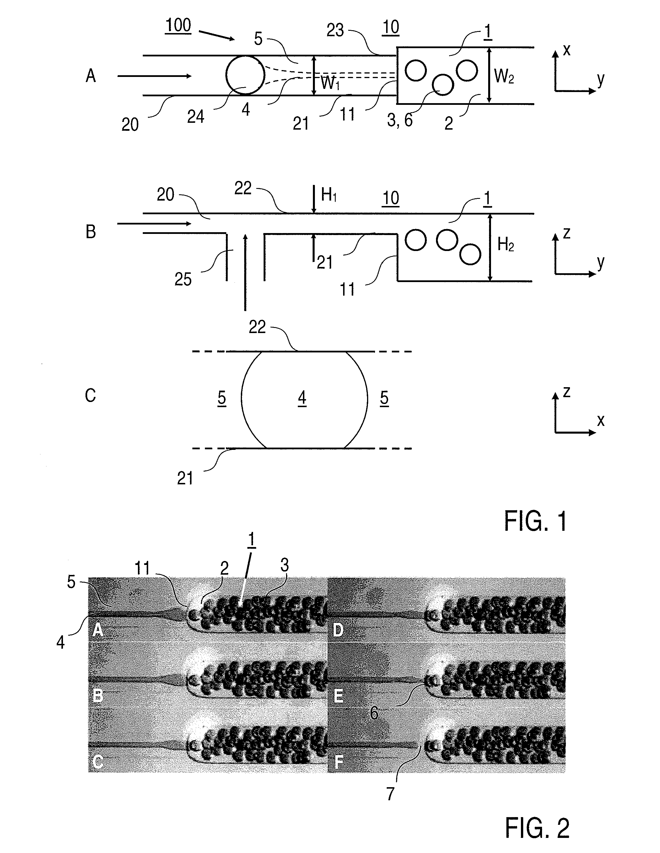
[0013]Advantageously, there is also no particular requirement with regard to the shape of the cross-sectional widening. The channel may widen in the dispersion region for example locally by a ramp shape of the bottom and / or top surfaces. According to a preferred embodiment of the invention, however, a stepped cross-sectional widening is provided. The dispersion region is formed by a step at which the channel height is increased from a first value, at which the dynamically
stable state is provided, to a second value, at which the dynamically unstable state is provided. One particular
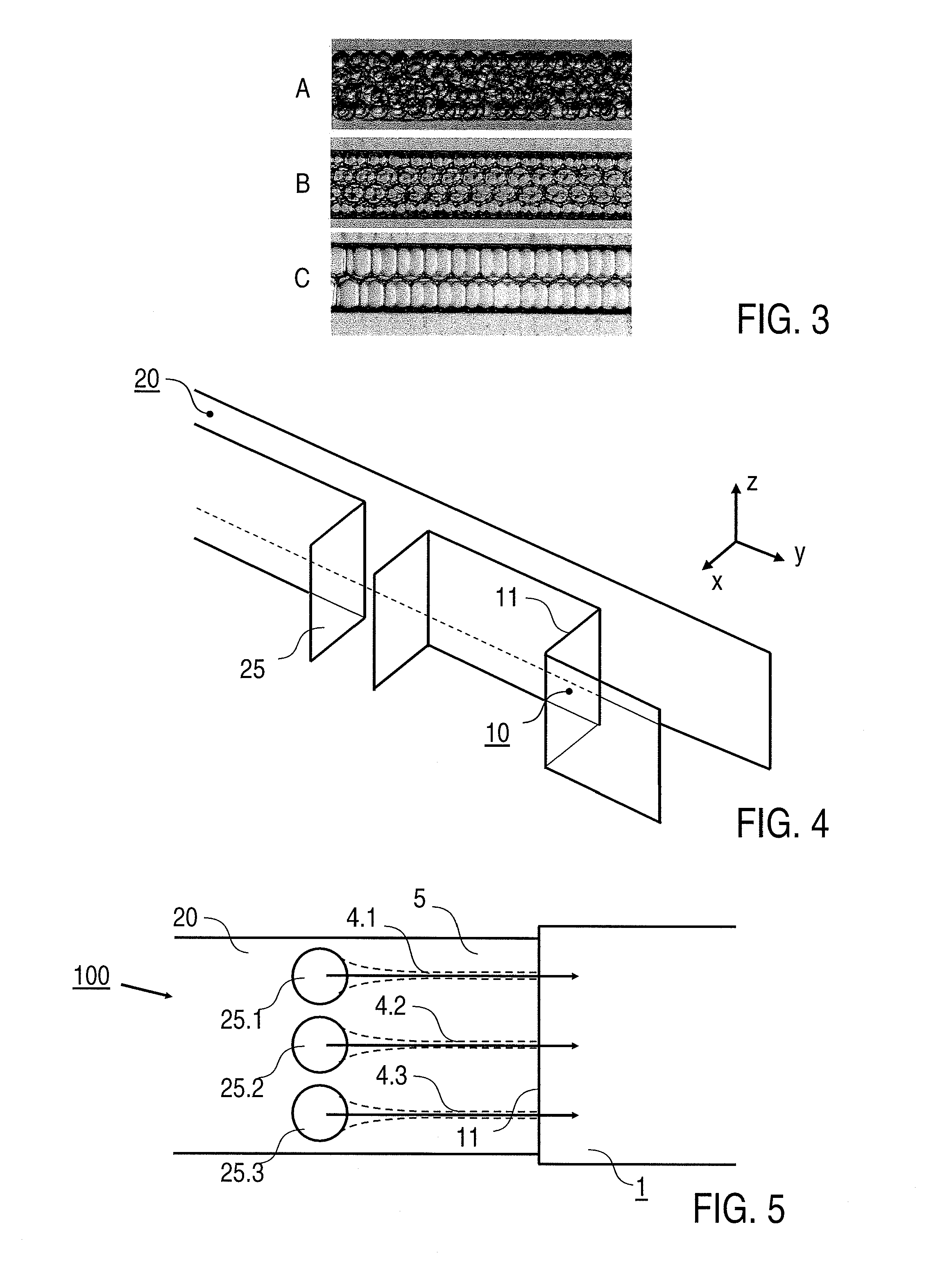
advantage of forming the emulsion at the stepped dispersion region consists in the improved monodispersity of the emulsion which, given a suitable choice of volumes of the continuous and dispersed phases, can be formed as a so-called crystalline emulsion.
[0018]Significant advantages of the method according to the invention compared to the conventional jet or shear techniques lie in the high degree of constancy of the
droplet size (monodispersity) of the dispersed phase and in the ability to set the volume ratio of the dispersed phase relative to the continuous phase. Preferably, the droplets of the dispersed phase have droplet diameters which are less than or equal to 1 mm. With particular preference, the diameters are less than 200 μm. As a result, particularly in the case of chemical or biochemical analyses, the substance consumption can advantageously be reduced and the analysis density can be increased. The droplet diameters depend in particular on the channel dimensions and on the ratio of the flow rates of the flows before the dispersion region.
[0019]One important
advantage of the droplet
diameter in the sub-mm range, which according to the invention can be achieved with a high degree of reproducibility, is the fact that the meta-
stable state of the composition consisting of the continuous and dispersed phase achieved by forming the emulsion has a sufficiently long life for practical uses of the microsystem. The droplets of the dispersed phase can remain as delimited compartments until the desired use, e.g. for analytical purposes. In order to stabilize the meta-stable state if necessary, surfactants (e.g.
sorbitan mono-oleate, CAS 1338-43-8) may be added to the liquids, e.g. to the continuous phase. However, it is not absolutely necessary to add surfactants. By way of example, emulsions of ferrofluids and water have proven to be extremely stable.
[0033]With regard to the method, the invention according to a further aspect is based on the general technical teaching of providing a method for
processing an emulsion containing droplets of the dispersed phase in the continuous phase in a fluidic microsystem, in particular the microsystem according to the invention, in which at least two droplets are fused when they are arranged on or move past at least two electrodes which are provided on a wall surface of the channel of the fluidic microsystem. Preferably, the fusion takes place by subjecting the electrodes to a
voltage pulse at the point in time when a first droplet is in electrical (ohmic or capacitive) contact with a first
electrode and an adjacent second droplet is in electrical (ohmic or capacitive) contact with a second
electrode. This means that the dispersed phase of the droplets directly touches the
electrode surface or is separated from the latter only by a lamella of the continuous phase which surrounds the droplets. Alternatively, an insulating layer, e.g. of a plastics material, may additionally be provided on the
electrode material (the electrode surface), as a result of which advantageous electrochemical side effects are avoided.

