
Piezoelectric ceramic, vibrator and ultrasonic motor

a technology of ultrasonic motors and piezoelectric ceramics, which is applied in the direction of generators/motors, impedence networks, basic electric elements, etc., can solve the problems of high material cost, low mechanical quality factor of knn-based piezoelectric ceramics, and difficulty in applying batiosub>3/sub>-based piezoelectric ceramics to the above uses, etc., to achieve excellent mechanical quality factor, reduce heat generation during driving, and reduce pb conten

Active Publication Date: 2011-05-17
TDK CORPARATION
View PDF5 Cites 15 Cited by
  • Summary
  • Abstract
  • Description
  • Claims
  • Application Information

AI Technical Summary

Benefits of technology

The present invention provides a piezoelectric ceramic with a reduced amount of Pb, excellent mechanical quality factor, and reduced heat generation during driving. The ceramic contains a compound represented by a specific formula and at least one element selected from Mn, Fe, or Cu in an amount of 0.04 to 0.6% by mass based on the main component. The ceramic can be used in vibrators and ultrasonic motors. The invention also provides a vibrator and an ultrasonic motor with the aforementioned piezoelectric ceramic.

Problems solved by technology

However, the BaTiO3-based piezoelectric ceramic has a low mechanical quality factor compared to the PZT-based and the PT-based piezoelectric ceramics.
It is therefore presently difficult to apply the BaTiO3-based piezoelectric ceramic to the aforementioned uses.
Furthermore, a KNN-based piezoelectric ceramic, since it uses a material containing Nb, has high material cost.
In addition to this problem, since alkaline metals such as K and Na are used, composition deviation during a sintering process is likely to occur.
Insufficient humidity resistance is another problem.
Furthermore, it has been found that, conventional piezoelectric ceramics, even though its mechanical quality factor is sufficiently improved, cannot suppress self-heating during driving, thereby changing piezoelectric properties.

Method used


Image

  • Piezoelectric ceramic, vibrator and ultrasonic motor
  • Piezoelectric ceramic, vibrator and ultrasonic motor
  • Piezoelectric ceramic, vibrator and ultrasonic motor

Examples


example 1

[0046]Commercially available BaCO3 powder, CaCO3 powder and TiO2 powder were prepared. These raw-material powders were sufficiently dried, weighed so as to obtain a composition ratio of Ca0.1Ba0.9TiO3, mixed well in an organic solvent by use of a ball mill and dried.

[0047]After dehydration, the mixture was sintered at 1000° C. for 2 hours to obtain Ca0.1Ba0.9TiO3 powder. The Ca0.1Ba0.9TiO3 powder thus obtained was pulverized by a ball mill until a particle size of 1 μm or less was obtained. MnCO3 was added in the mass ratio (in terms of Mn) to the Ca0.1Ba0.9TiO3, shown in Table 1 and mixed by a ball mill.

[0048]After mixed, polyvinyl alcohol (PVA) was added and uniaxially compacted at 1 MPa to obtain a pellet. The pellet was heated to 650° C. to remove a binder and sintered at a temperature within the range of 1250 to 1300° C. for 5 hours in an airtight system to obtain a sintered compact.

[0049]The sintered compact thus obtained was polished into a disk form having a diameter of 14 m...

examples 2 to 5

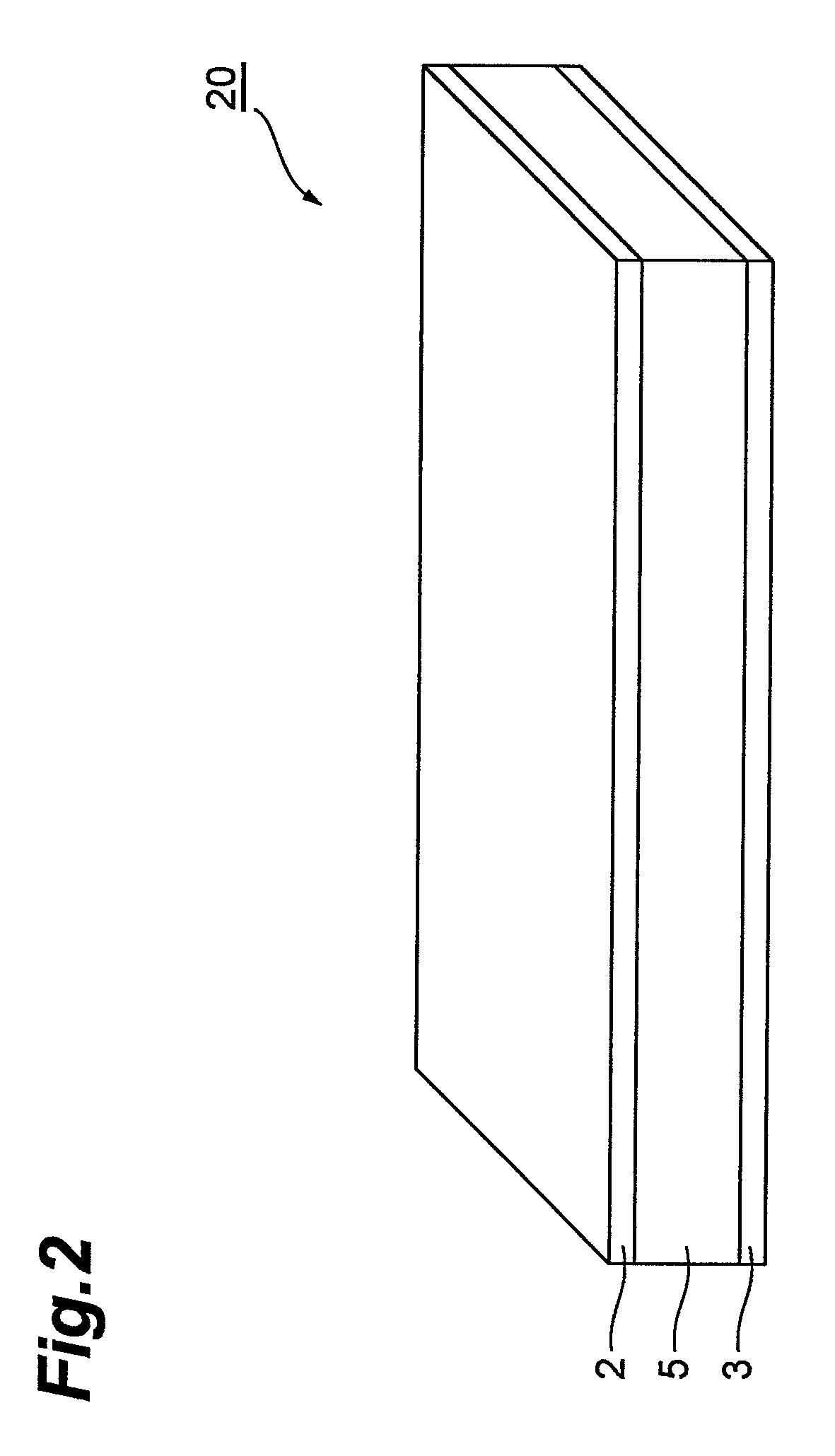
[0050]Each radial vibrator was manufactured in the same manner as in Example 1 except that the addition amount of MnCO3 in terms of Mn relative to Ca0.1Ba0.9TiO3 was changed to that shown in Table 1. These were regarded as the vibrators of Examples 2 to 5.

examples 6 to 9

[0051]Each radial vibrator was manufactured in the same manner as in Example 1 except that Fe2O3 was used in place of MnCO3 and added in the mass ratio (in terms of Fe) relative to Ca0.1Ba0.9TiO3 shown in Table 1. These were regarded as the vibrators of Examples 6 to 9.


PUM

PropertyMeasurementUnit
crystal grain sizeaaaaaaaaaa
particle sizeaaaaaaaaaa
temperatureaaaaaaaaaa

Abstract

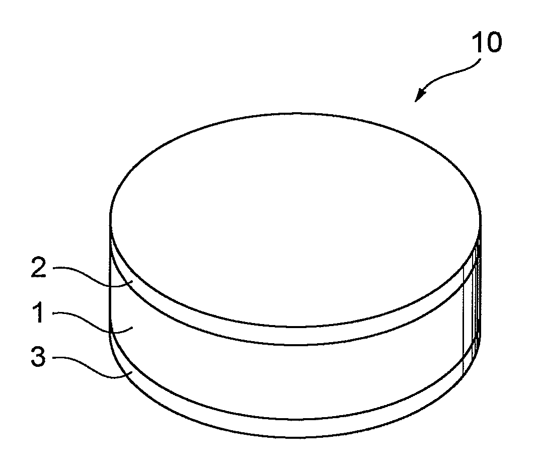
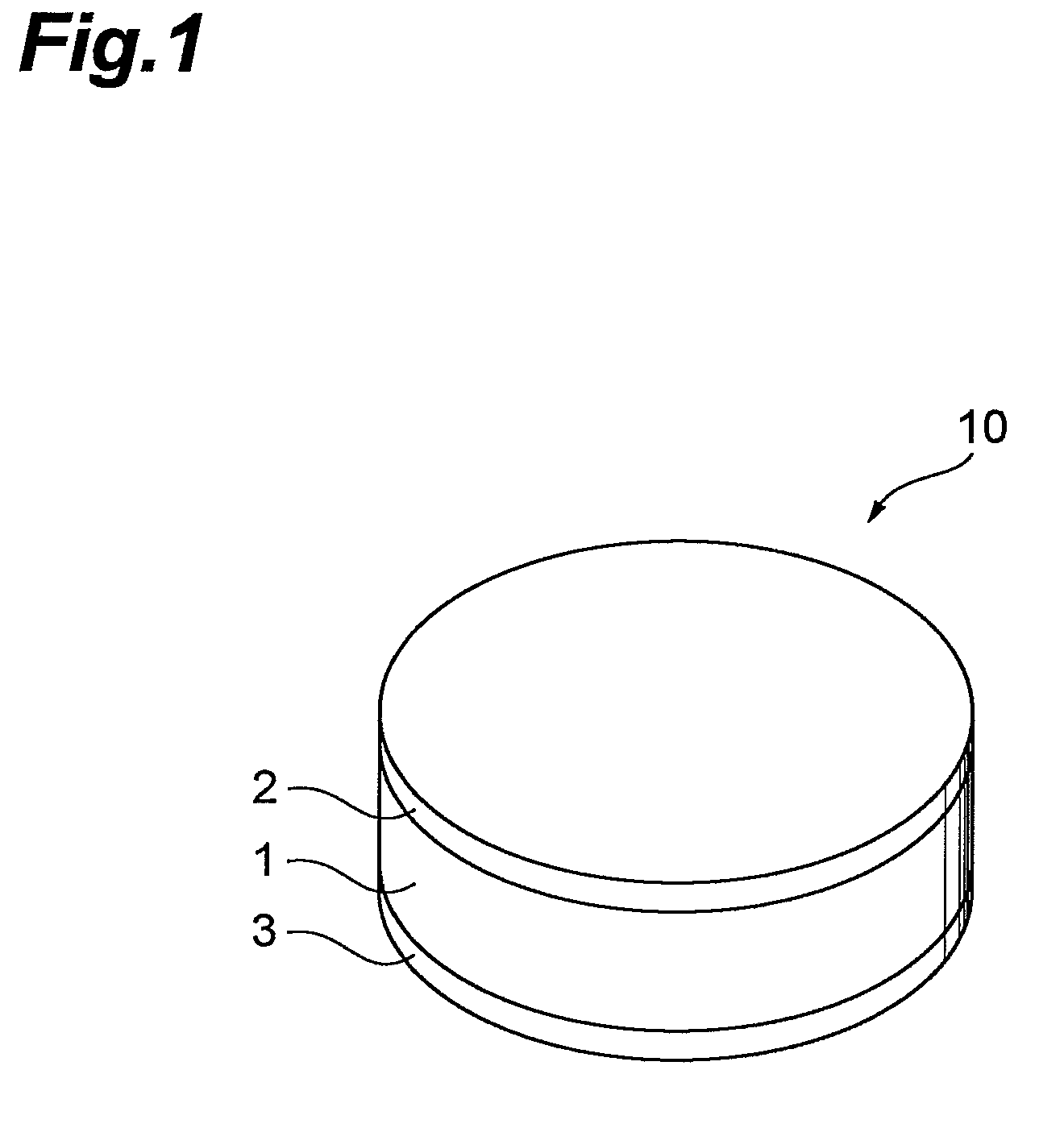
Provided is a piezoelectric ceramic 1 containing a compound represented by the following general formula (1), as a main component and at least one element selected from Mn, Fe and Cu in an amount of 0.04 to 0.6% by mass based on the main component, and a vibrator 10 having the piezoelectric ceramic 1 and electrodes 2, 3. CaxBa1−xTiO3  (1)where, x satisfies 0.05≦x≦0.20.

Description

BACKGROUND OF THE INVENTION[0001]1. Field of the Invention[0002]The present invention relates to a piezoelectric ceramic, a vibrator and an ultrasonic motor.[0003]2. Related Background Art[0004]Piezoelectric ceramics for use in ultrasonic motors, ultrasonic washers and piezoelectric transformers, and piezoelectric ceramics of piezoelectric actuators using resonance displacement are desired to have large resonance displacement and excellent piezoelectric properties. Particularly, when a piezoelectric ceramic is applied to the aforementioned uses, the drive frequency is high. Accordingly, if the mechanical quality factor (Qm) of the piezoelectric ceramic is low, heat easily generates and, for example, depolarization occurs and piezoelectric properties may change. For this reason, a piezoelectric ceramic having a sufficiently large mechanical quality factor (Qm) has been desired.[0005]As a piezoelectric ceramic satisfying such properties, a perovskite-type compound such as a PZT (PbZrO...

Claims


Application Information

Patent Timeline
Patent Type & Authority Patents(United States)
IPC IPC(8): H01L41/08C04B35/468H01L41/09H01L41/187H01L41/22H01L41/39H03H9/17
CPCC04B35/4682C04B35/62685H01L41/1871H02N2/163C04B2235/5445C04B2235/3236C04B2235/3262C04B2235/3272C04B2235/3281C04B2235/3208H10N30/8536
Inventor TANAKA, DAISUKETSUKADA, TAKEOFURUKAWA, MASAHITO
Owner TDK CORPARATION
Learn More