Method for joining two objects and corresponding joining element

a technology of joining elements and objects, applied in the field of joining two objects and corresponding joining elements, can solve the problems of unsatisfactory or not even satisfactory, effect needs to be counterbalanced, and characteristics of vibration transmission are not optimal, so as to improve the coupling of mechanical vibration

Active Publication Date: 2011-05-31
WOODWELDING
View PDF8 Cites 22 Cited by
  • Summary
  • Abstract
  • Description
  • Claims
  • Application Information

AI Technical Summary

Benefits of technology

[0016]The joining element is designed to allow improved coupling of mechanical vibration from the object facing the excitable element during at least part of the joining action (asymmetric anchoring action).
[0017]By applying at least one of the above named measures and therewith adapting the joining element and / or the recess provided for the joining element, it becomes possible to achieve satisfactory joints for a much wider range of applications than is possible by using the teaching of the publication WO 96 / 01377. However, for each different application, experiments are to be carried out to find optimum conditions for achieving a joint as desired.

Problems solved by technology

In most cases this is due to the fact that either the joining element is anchored in the object facing the excitable element in a satisfactory way while anchorage in the other object is not satisfactory, or the joining element end in the object facing the excitable element or the material surrounding this joining element end suffers from overheating, while anchorage in the other object is either satisfactory or not even satisfactory.
This effect needs to be counterbalanced if it is not to render the joint quality unsatisfactory e.g. by unsatisfactory anchorage at the distal joining element.
It is further due to the need of the mechanical vibration to reach the distal joining element end by being transmitted through the joining element itself, wherein the characteristics for vibration transmission are not optimal, particularly when there is liquefied material at the proximal end of the joining element.
However, such two step method needs more time for the complete joining action and more complicated devices if it needs to be carried out fully automatically.
Therefore, such two step method is not the inventive solution to the problem.

Method used


Image

  • Method for joining two objects and corresponding joining element
  • Method for joining two objects and corresponding joining element
  • Method for joining two objects and corresponding joining element

Examples


Embodiment Construction

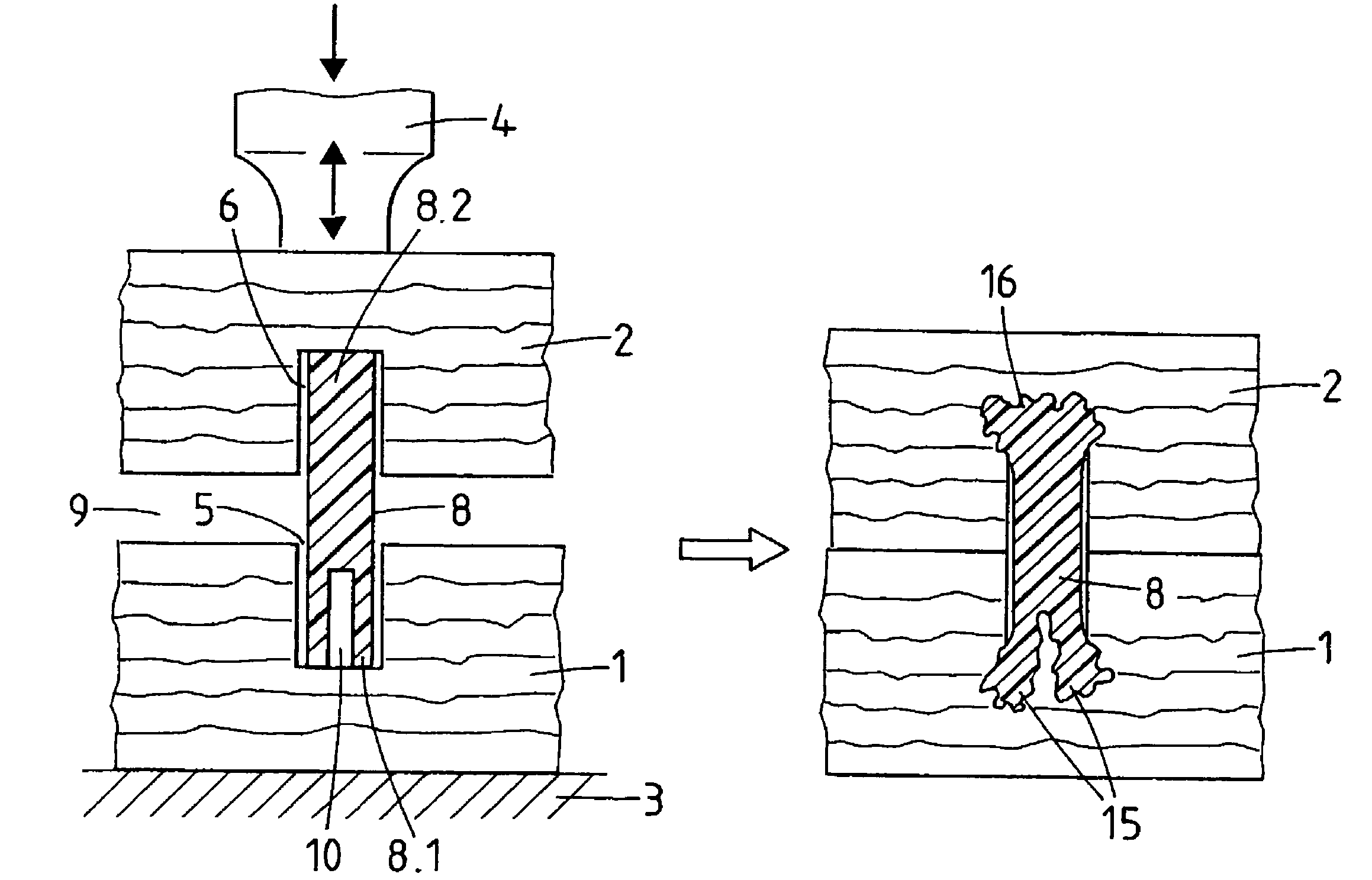
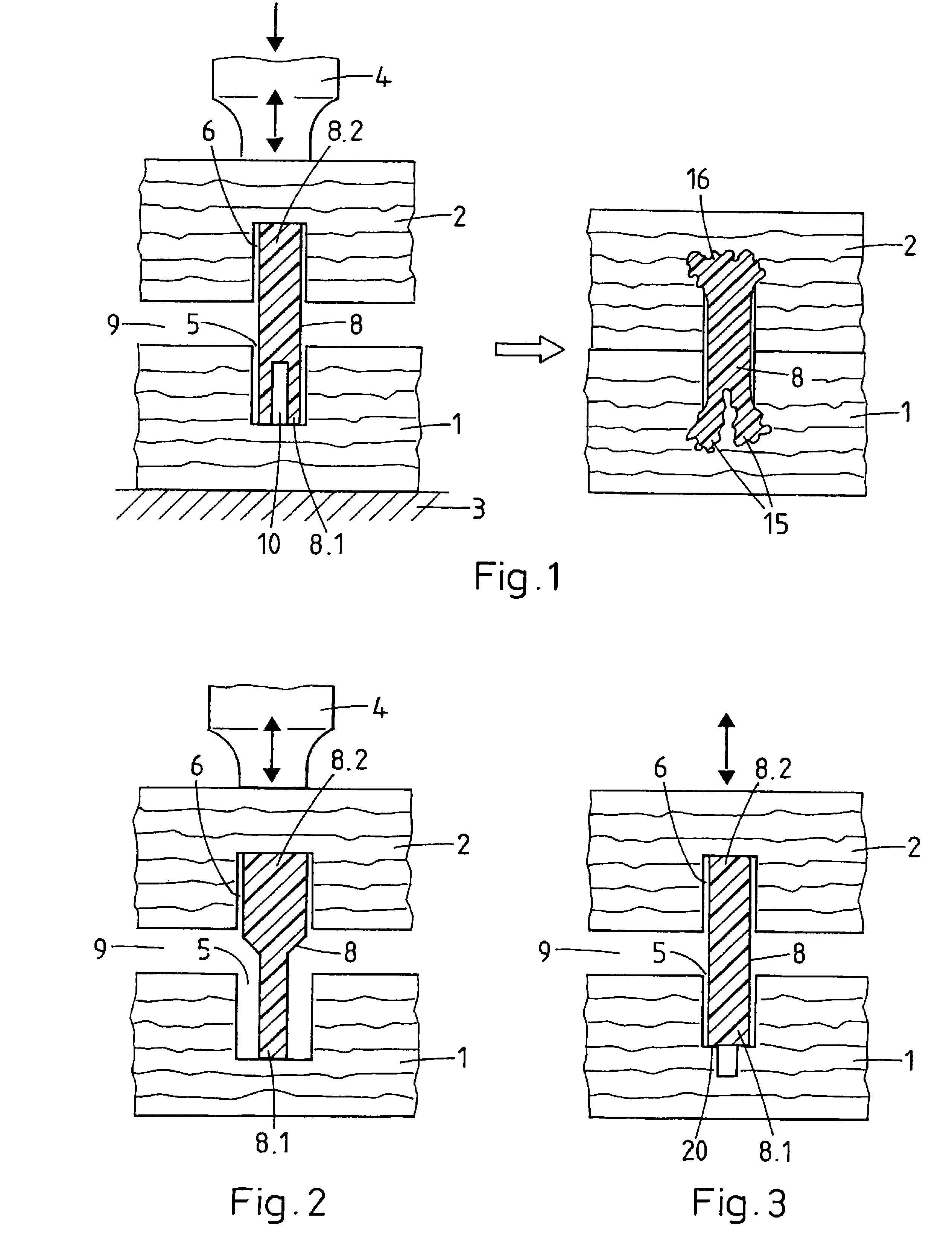
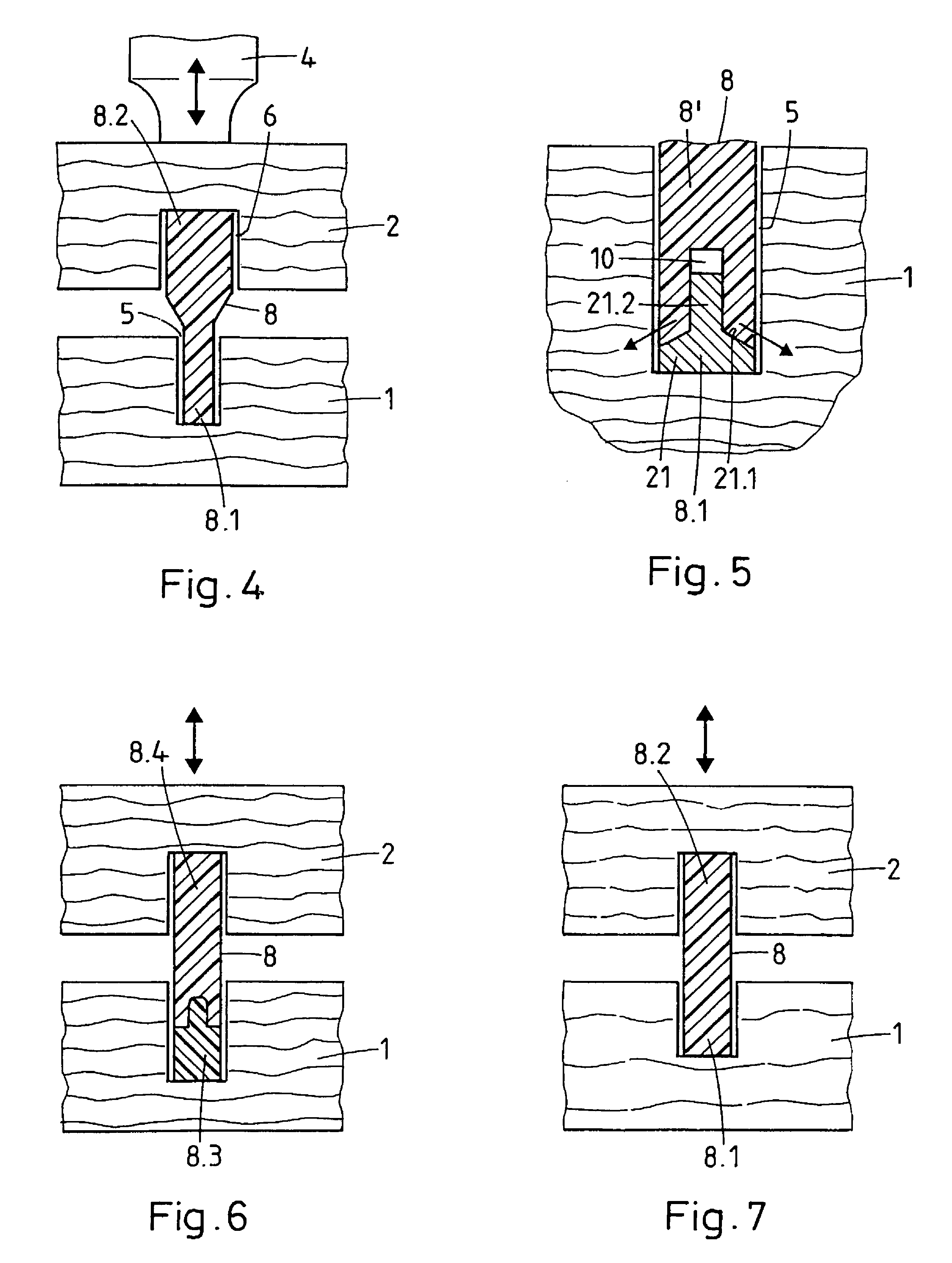
[0029]FIG. 1 shows the method according to the invention using a first exemplary embodiment of an asymmetric joining element and a pair of identical blind holes (identical regarding bottom face, not necessarily regarding depth) provided as recess between the two objects to be joined. Joining element and objects to be joined are shown in section parallel to the direction of the applied pressing force, i.e. parallel to a line connecting the proximal and the distal joining element ends. The two objects are e.g. wooden boards or chipboard elements or consist of another porous material. The assembly is shown both before application of pressure and vibration (left hand side) and after application of pressure and vibration (right hand side).

[0030]For joining the two objects 1 and 2, they are positioned between a support 3 and an excitable element 4 (e.g. sonotrode of an ultrasonic device), the first object 1 on the side of the support 3 and the second object 2 on the side of the excitable ...


PUM

PropertyMeasurementUnit
thermoplastic propertiesaaaaaaaaaa
temperatureaaaaaaaaaa
densityaaaaaaaaaa

Abstract

A first and a second object (1 and 2) are joined with the aid of a joining element (8) including at least in the region of its distal and proximal ends (8.1 and 8.2) a thermoplastic material. Two blind holes (5 and 6) facing each other are provided in the two objects (1 and 2) and the joining element (8) is positioned in the blind holes such that its distal and proximal ends (8.1) are in contact with the bottom faces of the blind holes and such that there is a gap (9) between the two objects (1 and 2). This assembly is then positioned between a support (3) and a sonotrode (4). The sonotrode (4) and the support (3) are forced towards each other, while the sonotrode (4) is vibrated, thereby liquefying at least part of the material having thermoplastic properties, there, where the joining element ends (8.1 and 8.2) are pressed against the bottom faces of the holes (5 and 6) and allowing the liquefied material to infiltrate into pores of the hole surfaces or unevennesses or openings provided in the hole surfaces.

Description

BACKGROUND OF THE INVENTION[0001]1. Field of the Invention[0002]The invention concerns a method for joining two objects and a corresponding joining element being applicable to the method, wherein the joining element consists at least partly of a material having thermoplastic properties and the method comprises the application of mechanical vibration, e.g. ultrasonic vibration.[0003]2. Description of Related Art[0004]Publications WO 98 / 42988 and WO 00 / 79137 describe joining elements which consist at least partly of a material with thermoplastic properties and which are, for example, pin-shaped. Such a joining element is anchored in an object of a porous material by positioning it in a blind hole provided in the object or by forcing it through the surface of the object and by then applying mechanical vibration (e.g. ultrasonic vibration) to the joining element while simultaneously pressing it further into the object. Due to the mechanical vibration, the thermoplastic material of the j...

Claims


Application Information

Patent Timeline
Patent Type & Authority Patents(United States)
IPC IPC(8): B23P17/00B29C65/00B29C65/08B29C65/60F16B5/08
CPCB29C66/43421B29C66/8322B29C66/83221F16B5/08B29C65/564B29C65/604B29C66/524B29C65/606Y10T29/49947B29C66/322B29C66/47B29C66/7487B29K2711/14B29C66/30326Y10T29/49908B29C65/08B29C66/526Y10T29/49945Y10T29/49938Y10T16/95Y10T29/49936Y10T403/477Y10T29/49911Y10T29/49954Y10T156/109Y10T29/4992Y10T29/49952B29C65/00B29K2995/0068B29C66/636B29C66/12441B29C66/126B29C66/112B29C66/1122B29C66/114B29C66/1142
Inventor CLINCH, COLINAESCHLIMANN, MARCELTORRIANI, LAURENTMOCK, ELMAR
Owner WOODWELDING
Why Eureka
Try Eureka