
Single stage root type-vacuum pump and vacuum fluid transport system employing the single stage root type-vacuum pump

a vacuum pump and vacuum fluid technology, applied in the direction of machines/engines, rotary/oscillating piston pump components, liquid fuel engines, etc., can solve the problems of poor vacuum generation efficiency, increased running costs when generating a high degree of vacuum, and difficulty in compact vacuum stations. , to achieve the effect of improving volume efficiency, reducing internal leakage, and increasing the amount of outside air inflow

Inactive Publication Date: 2011-05-31
SEKISUI CHEM CO LTD
View PDF17 Cites 4 Cited by
  • Summary
  • Abstract
  • Description
  • Claims
  • Application Information

AI Technical Summary

Benefits of technology

The present invention provides a single stage root type-vacuum pump that can achieve fine anti-corrosion properties while suppressing an increase in installation space. The pump includes a suction port and a discharge port, and performs normal rotation and reverse rotation. The pump includes enclosed spaces that are surrounded by adjacent lobes of rotors and the inner wall surface of the casing, and an outside air introduction hole in a horizontally long slit shape, parallel to the width direction of the casing. The pump is made of a Ni-resist cast iron-type corrosion-resistant material having a small rate of thermal expansion. The vacuum fluid transport system employing the pump has expanded the collectable range of sewage and can offer a vacuum fluid transport system that can collect sewage or the like to a relatively wide area.

Problems solved by technology

Accordingly, it has been difficult to make the vacuum station compact.
However, the vacuum station 1 using the above-described conventional ejector type vacuum generation apparatus thus configured has poorer efficiency of vacuum generation than a water seal vacuum pump, and has a problem of an increase in running costs when generating a high degree of vacuum.
Accordingly, there is a problem in that a pumping flow rate is reduced at the time of reverse rotation.
Meanwhile, in a vacuum sewage system, even in a case where a surface treatment such as coating is applied to a vacuum sewage system, such surface treatment alone is not sufficient to prevent the corrosion from progressing under the conditions that hydrogen sulfide is generated in sewage and the gas is continuously vacuumed for a long time period.
Hence, the coating or the like needs to be repaired at the time of overhauling, which requires a long period of time and cannot avoid a cost increase.

Method used


Image

  • Single stage root type-vacuum pump and vacuum fluid transport system employing the single stage root type-vacuum pump
  • Single stage root type-vacuum pump and vacuum fluid transport system employing the single stage root type-vacuum pump
  • Single stage root type-vacuum pump and vacuum fluid transport system employing the single stage root type-vacuum pump

Examples


embodiments

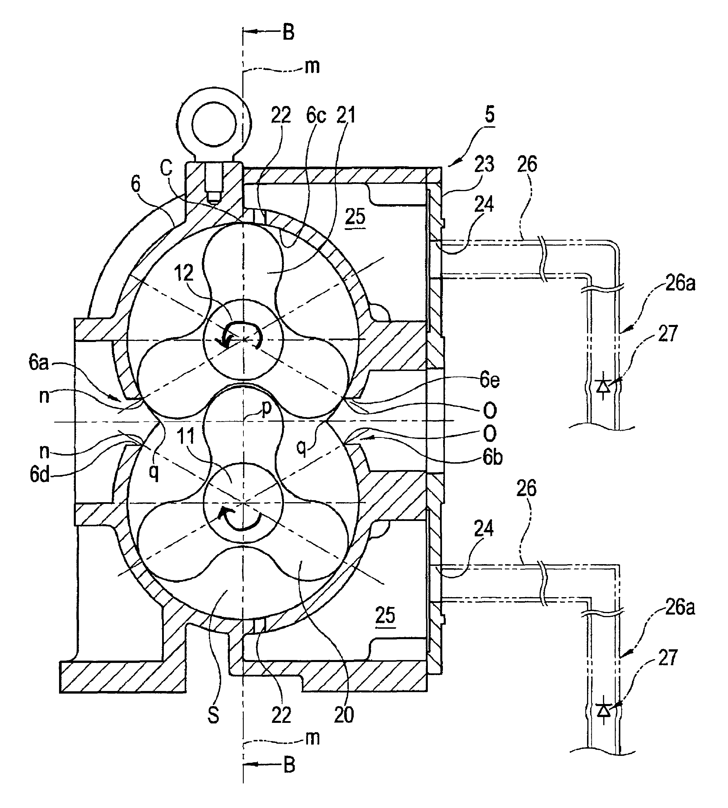
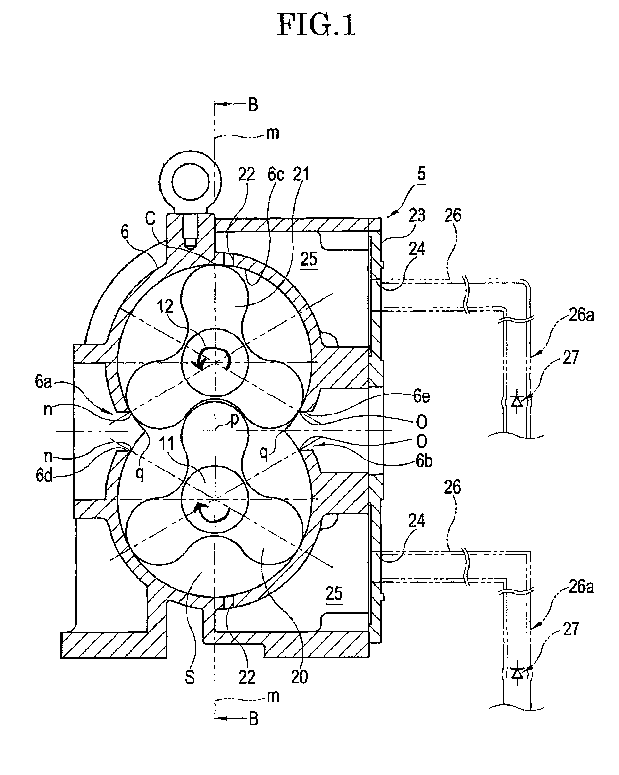
[0050]A structure of a single stage root type-vacuum pump will be explained by using FIG. 1 to FIG. 4 to begin with. A single stage root type-vacuum pump 5 is placed as the single stage root type-vacuum pump on an upper part of a set base 10 in which a driving motor M is provided as a drive force as shown in FIG. 3 or FIG. 4.

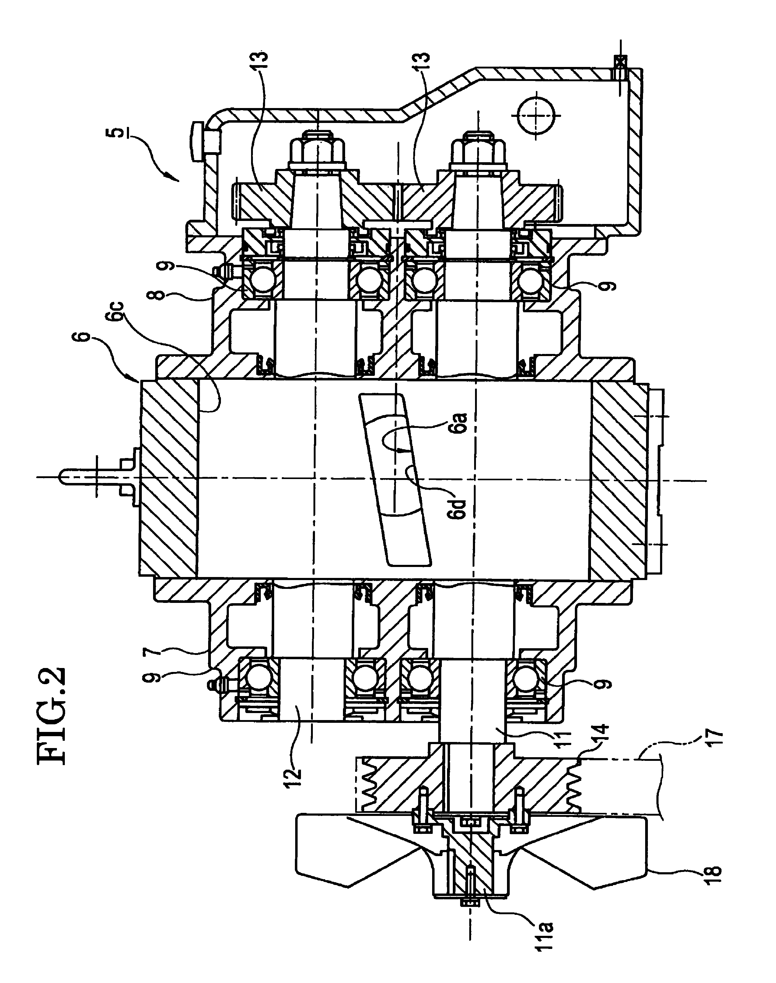
[0051]As shown in FIG. 2, mainly in this single stage root type-vacuum pump 5, a pulley side housing 7 and a gear side housing 8 are fitted to both sides of a casing 6, and two parallel shafts of a driving side root type-rotor shaft 11 and a driven side root type-rotor shaft 12 are rotatably supported by bearings 9 and others which are inserted to the respective housings 7 and 8.

[0052]Meanwhile, timing gears 13 and 13 engaged with each other are fitted to respective shaft ends of the driving side root type-shaft 11 and the driven side root type-rotor shaft 12 protruding from the gear side housing 8.

[0053]Moreover, a tip end portion 11a of the driving side root t...

example 1

[0074]It was confirmed when applying the single stage root type-vacuum pump 5 having the above-described features to a vacuum fluid transport system including a vacuum station system, that require d time for increasing a degree of vacuum is reduced, that it is possible to extend a collectable distance of sewage, and that energy is saved.

[0075]FIG. 5 shows a vacuum fluid transport system employing the single stage root type-vacuum pump according to Example 1 of the embodiment of this invention.

[0076]Here, explanation will be made by using the same reference numerals for identical and equivalent portions to those in the embodiment.

[0077]A structure will be explained to begin with. In the vacuum station system of this Example 1, a pipe 32 is laid for allowing sewage W, discharged from a household I or the like, to flow by gravity flow into a manhole apparatus H installed for each household or for several households.

[0078]A large float valve 34 is installed at a lower part of a cesspit ...


PUM


Abstract

A single stage root type vacuum pump has a pair of outside air introduction holes formed in the vicinity of a phantom line in an inner wall surface within a range between intersecting points, where the intermediate position that is located between the center of a driving side rotor shaft and the center of a driven side rotor shaft of three-lobe rotors intersects with the intersecting points at which internal circles located on the extended circumferences of the inner wall surface of the casing. The pair of outside air introduction holes formed in symmetrical positions into horizontally long slit shapes parallel to a width direction of the casing. Check valves are fitted to tip end portions of outside air introduction pipes which are respectively connected to outside air communication holes for preventing air from escaping at the time of reverse rotation of the three-lobe rotors.

Description

TECHNICAL FIELD[0001]The present invention relates to a single stage root type-vacuum pump used, for example, in a vacuum sewage system for transporting sewage discharged from households, factories and the like, and to a vacuum fluid transport system employing this single stage root type-vacuum pump.BACKGROUND ART[0002]There are conventionally known a water seal vacuum pump and an ejector type as a vacuum generation apparatus for a vacuum station (a relay pump station) for generating a vacuum pressure to be applied to a vacuum pipeline in a vacuum sewage system.[0003]Concerning a vacuum station 1 employing an ejector type vacuum generation apparatus, one shown in FIG. 8 has been known (see Japanese Patent No. 3702760 (paragraphs 0015 to 0032 and FIG. 1, for example)).[0004]This station is configured so that sewage in a sewage tank 2 which is buried under a road or the like is ejected from an ejector 4 and is circulated by a sewage circulation pump 3 inside this sewage tank 2. Hence,...

Claims


Application Information

Patent Timeline
Patent Type & Authority Patents(United States)
IPC IPC(8): F04C2/00F04C28/18
CPCF01C21/007F04C18/126F04C29/12F04C28/04F04C2250/101F04C2220/10
Inventor OHTSUKA, TETSUSHIITO, YOSINOBU
Owner SEKISUI CHEM CO LTD
Learn More