Cladding material and its manufacturing method, press-forming method, and heat sink using cladding material

a technology of cladding material and manufacturing method, which is applied in the field of cladding material and its manufacturing method, press-forming method, and heat sink using cladding material, can solve the problems of insufficient thermal conductivity of above-mentioned cladding material, low thermal expansion coefficient and higher thermal conductivity, and heat distortion or camber generated in this heat sink. , to achieve the effect of low thermal expansion coefficient, easy fabrication and high thermal conductivity

Active Publication Date: 2011-05-31
TSUSHIMA EIKI
View PDF29 Cites 11 Cited by
  • Summary
  • Abstract
  • Description
  • Claims
  • Application Information

AI Technical Summary

Benefits of technology

Since this invention is constituted as mentioned above, a cladding material with both high thermal conductivity and low thermal expansion coefficient can be obtained. This cladding material can be easily fabricated by the manufacturing method of this invention. Since this cladding material is excellent in workability, it can be easily patterned by the press forming method of this invention, and by these, a heat sink for semiconductor devices with excellent heat dissipation nature can be obtained at low cost.

Problems solved by technology

Therefore, at room temperature, heat distortion or camber is generated in this heat sink.
However, recent semiconductor device becomes high powered, and on the material of heat sinks on which these devices are mounted, low thermal expansion coefficient and higher thermal conductivity are needed.
For this requirement, thermal conductivity of above mentioned cladding materials is not enough.
Mo is harder than Cu and hard to be patterned mechanically, therefore, the workability of the cladding material with large volume ratio of Mo gets worse, and fabrication using press punching method etc., which is suitable press forming method for mass production, is hard to be applied.
Therefore, other press forming methods at high cost are required for this patterning, therefore, products using this cladding material becomes expensive.
Therefore, it was difficult to obtain a cladding material with both high thermal conductivity and low thermal expansion coefficient at low cost.

Method used


Image

  • Cladding material and its manufacturing method, press-forming method, and heat sink using cladding material
  • Cladding material and its manufacturing method, press-forming method, and heat sink using cladding material
  • Cladding material and its manufacturing method, press-forming method, and heat sink using cladding material

Examples


example

Below, examples of this invention are described with comparative examples.

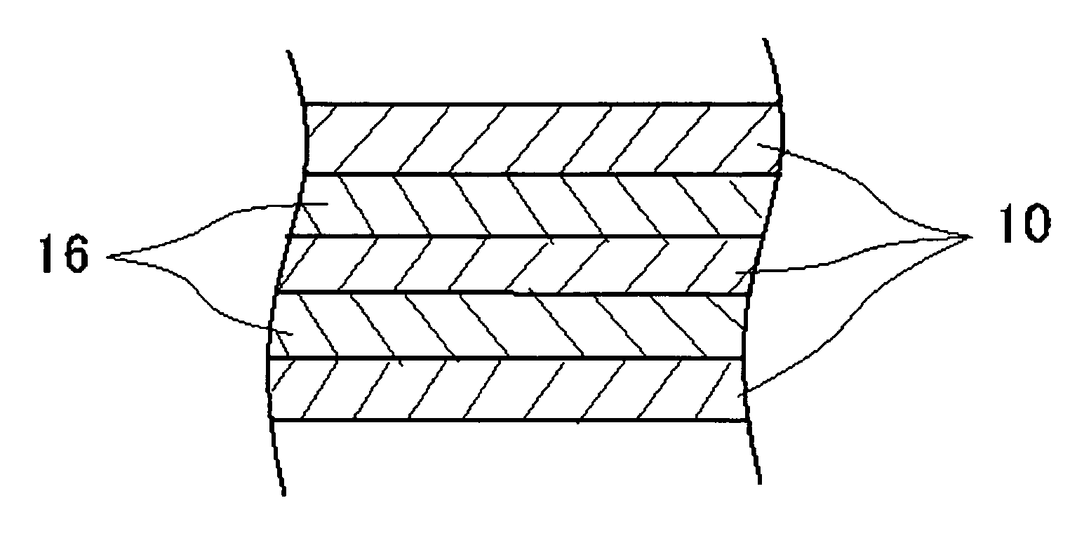
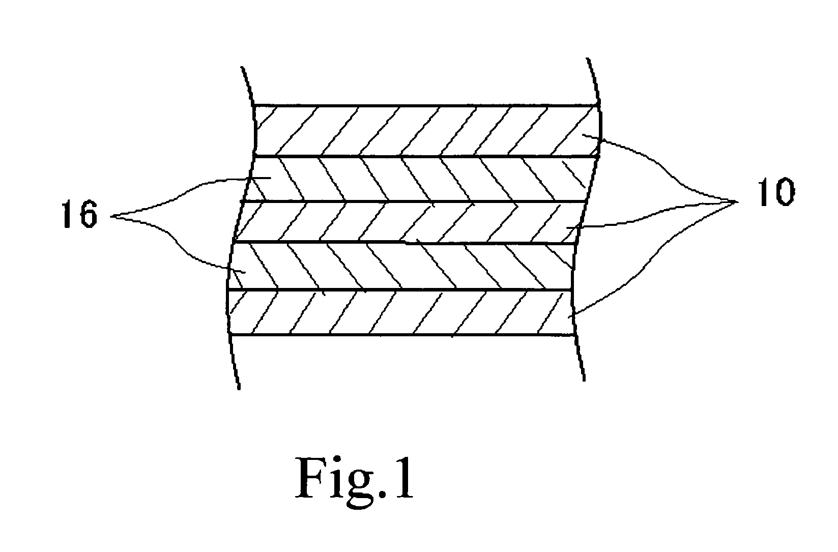
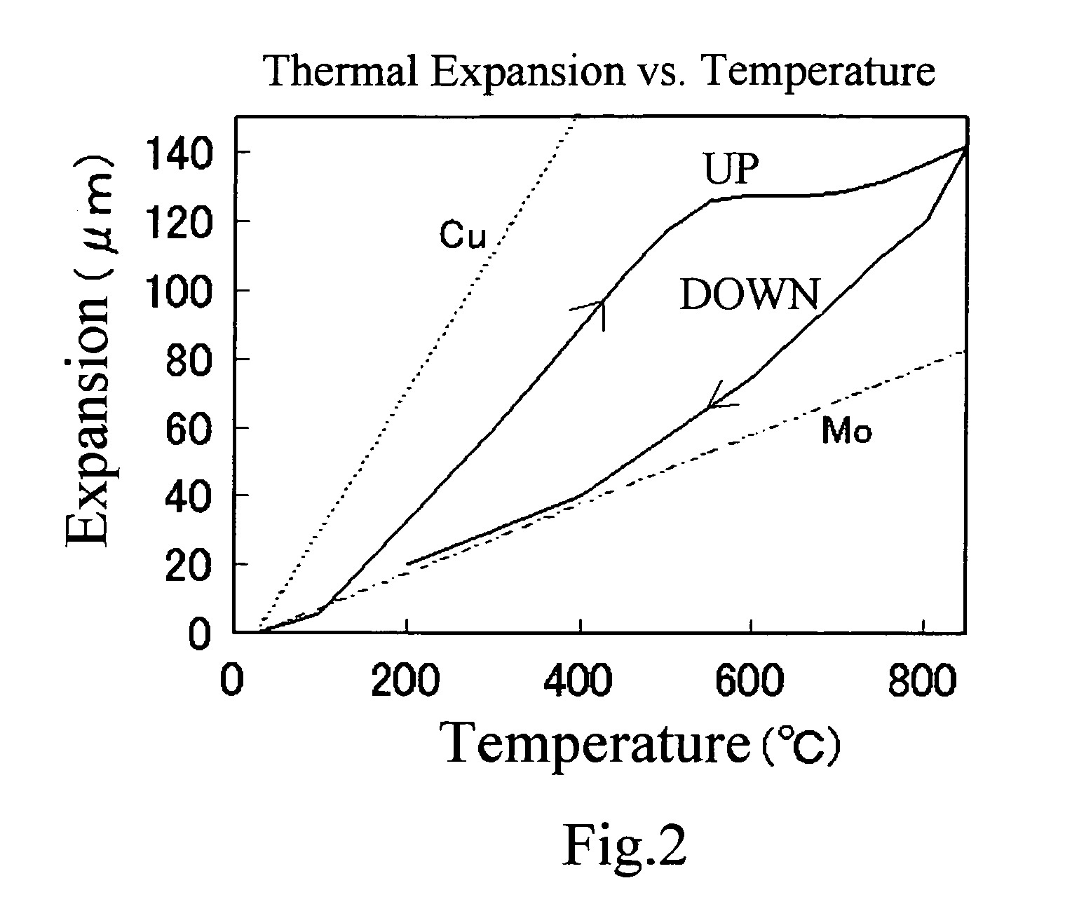
As lamination structures composed of Cu and Mo as examples of this invention, the cladding materials in which the number of layers and the thickness of each layer were varied, were fabricated as examples 1-15. On the other hand, the cladding materials in which the thickness of each layer of the 3-layered structure of Cu / Mo / Cu was varied, were fabricated as comparative examples 1-15 as comparative examples. The thermal expansion coefficient and the thermal conductivity in these samples were measured. All examples and all comparative examples were fabricated by the manufacturing method shown in FIG. 3. The thermal expansion coefficients were calculated as averages while cooling from 850° C. to 30° C. in argon atmosphere, using Dilato Meter made by MAC Science co., ltd, by a procedure described in JISH7404. Each sample used for measurement of thermal expansion coefficient was made into the size of 20 mm (length)×...


PUM

PropertyMeasurementUnit
thicknessaaaaaaaaaa
volume ratioaaaaaaaaaa
thermal conductivityaaaaaaaaaa

Abstract

Recent semiconductor device becomes high powered, and on the material of heat sinks on which these devices are mounted, lower thermal expansion coefficient and higher thermal conductivity are needed. For this requirement, material with thermal conductivity as high as Cu alone and also with low thermal expansion coefficient, is needed. An aspect in accordance with the present invention provides, a cladding material in which 1st material layer and 2nd material layer are laminated alternately, wherein thermal expansion coefficient of said 2nd material is lower than the thermal expansion coefficient of said 1st material, and thermal conductivity of said 2nd material is lower than the thermal conductivity of said 1st material, and a total number of laminated layers composed of said 1st material and said 2nd material is 5 or more.

Description

CROSS-REFERENCE TO RELATED APPLICATIONSThe present application is a 35 U.S.C. 371 national stage entry of PCT / JP2006 / 310441, filed May 25, 2006, and claims priority from Japanese Patent Application No. 2005-302590, filed Oct. 18, 2005, the contents of which are herein incorporated by reference in their entirety.BACKGROUND OF THE INVENTION1. Field of the InventionThis invention relates to a heat sink material used for semiconductor devices, especially to a cladding material used for a heat sink on which LSIs, ICs, power transistors are mounted and are operated with high power, and also relates to its manufacturing method, to a press forming method for the cladding material, and to a heat sink using the cladding material.2. Description of the Related ArtFor heat sinks on which semiconductor devices, especially LSIs, ICs, power transistors operated with high power, are mounted, efficient dissipation of heat generated by these semiconductor devices is required.Therefore, high mechanical...

Claims


Application Information

Patent Timeline
Patent Type & Authority Patents(United States)
IPC IPC(8): B32B15/01B23K20/00H01L23/36
CPCB23K20/02B32B15/01B32B15/018H01L23/3735B23K20/04Y10T428/12632B23K2201/18B23K2201/36B23K2203/08B23K2203/16B23K2203/18H01L2924/0002Y10T428/12806Y10T428/12903Y10T428/12778H01L2924/00B23K2101/18B23K2101/36B23K2103/08B23K2103/12B23K2103/18B23K20/00B23K20/22H01L23/373
Inventor TSUSHIMA, EIKI
Owner TSUSHIMA EIKI
Why Eureka
Try Eureka