Feedback enhanced plasma spray tool

a plasma spray tool and plasma technology, applied in the field of plasma spraying devices, can solve the problems of not being able to provide enough, not being able to reliably design parts with tightly specified engineered coating structures, and no tool has been available to improve the control of these coating parameters, so as to achieve more tightly controlled coating thickness, maintain control over other variables, and increase coating deposition rate

Inactive Publication Date: 2011-05-31
CYBER MATERIALS
View PDF2 Cites 10 Cited by
  • Summary
  • Abstract
  • Description
  • Claims
  • Application Information

AI Technical Summary

Benefits of technology

It is an advantage of the present application that process variations caused by torch wear or aging can be detected and compensated by taking measurements and making adjustments throughout a deposition run;
It is a further advantage of the present application that deposition rate can be maintained by adjusting the feedstock rate from feed sources including powders, liquids, suspensions of powders in liquids, or wire.

Problems solved by technology

The industry has therefore not been able to reliably design parts with tightly specified engineered coating structures or to reproduceably provide a desired porosity, crack density, and grain structure.
Nor has the industry been able to consistently provide sufficient control over sprayed layers so different materials could be provided with tightly specified properties and thicknesses or so layers with varying composition were deposited.
And no tool has been available that provides improved control over these coating parameters while providing a high deposition rate to reduce cost of sprayed layers.

Method used


Image

  • Feedback enhanced plasma spray tool
  • Feedback enhanced plasma spray tool
  • Feedback enhanced plasma spray tool

Examples


Embodiment Construction

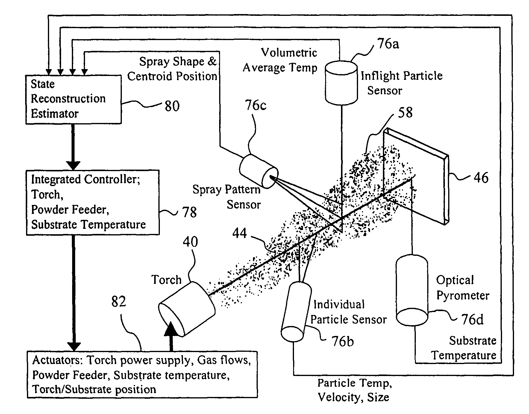
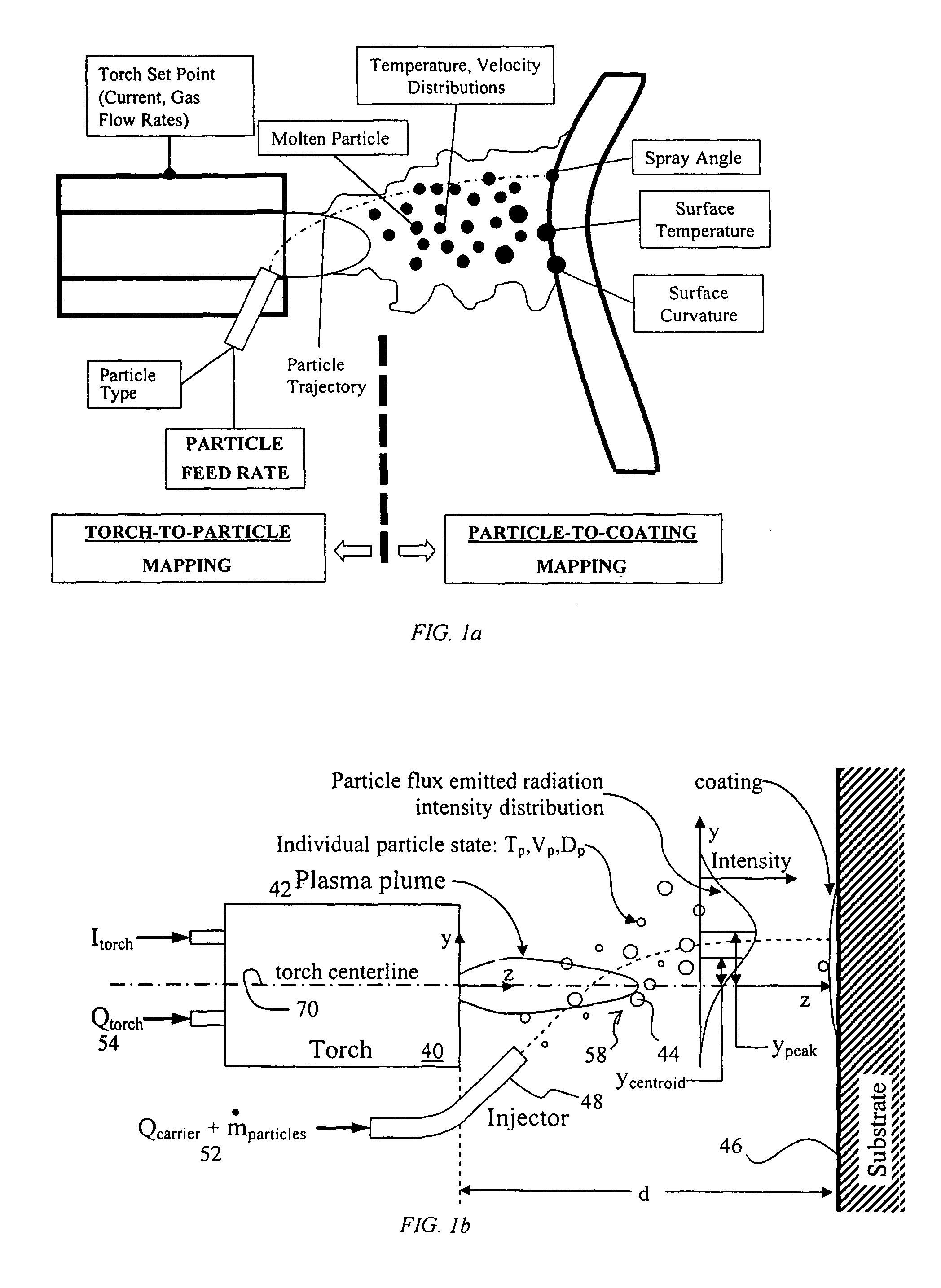
Important input and output process variables of a plasma spray process are schematically illustrated in FIGS. 1a, 1b, showing torch 40, plasma jet or plume 42, and particles 44 traveling from torch 40 to surface 46. Particles 44 are introduced into torch 40 as a powder through injector tube 48 along side 50 of torch 40. Carrier gas 52 carriers particles 44 of the powder through tube 48 and into torch 40. Alternatively, wire, liquid or suspension can be used for introducing feed material. Particles 44 are accelerated when they enter plasma jet 42 that passes through torch 44. Particles 44 are heated as they cross through plasma jet 42. Some of the particles are heated enough to melt, to provide that a substantial fraction of particles 44 are molten particles 56. Spatial distribution of particles 58 varies with distance from torch 40. Spatial distribution of particles 58 is affected by flow rate of carrier gas 52 among other conditions of the plasma jet 42.

Torch 40 includes several to...


PUM

PropertyMeasurementUnit
particle sizeaaaaaaaaaa
temperatureaaaaaaaaaa

Abstract

An improved automatic feedback control scheme enhances plasma spraying of powdered material through reduction of process variability and providing better ability to engineer coating structure. The present inventors discovered that controlling centroid position of the spatial distribution along with other output parameters, such as particle temperature, particle velocity, and molten mass flux rate, vastly increases control over the sprayed coating structure, including vertical and horizontal cracks, voids, and porosity. It also allows improved control over graded layers or compositionally varying layers of material, reduces variations, including variation in coating thickness, and allows increasing deposition rate. Various measurement and system control schemes are provided.

Description

FIELDThis application generally relates to a device for spraying a material. More particularly, it relates to a device for plasma spraying a powdered material. Even more particularly, it relates to a device that includes sensors and feedback for enhanced plasma spraying of the powdered material.BACKGROUNDPlasma spray is used in manufacturing operations in aerospace, energy, engine, electronic, and biomedical because it can economically produce engineered coatings that protect against wear, reduce friction, and reduce corrosion. The plasma spray coatings are also particularly suited to protect underlying metals against high temperature environments, such as in jet engines. Either ceramic or metallic coatings can be formed with plasma spray. However, up until now parts coated with plasma spray have varied substantially from each other. The industry has therefore not been able to reliably design parts with tightly specified engineered coating structures or to reproduceably provide a de...

Claims


Application Information

Patent Timeline
Patent Type & Authority Patents(United States)
IPC IPC(8): B23K10/00B23K10/02H05H1/34
CPCB05B12/082B05B12/10B23K10/006C23C4/127B23K10/027Y02T50/67H05H2001/3494C23C4/134H05H1/3494Y02T50/60
Inventor GEVELBER, MICHAEL ALANWROBLEWSKI, DONALD EDWARD
Owner CYBER MATERIALS
Why Eureka
Try Eureka