Plasma source with discharge inducing bridge and plasma processing system using the same
a plasma processing system and discharge inducing bridge technology, applied in the field of radio frequency plasma sources, can solve the problems of increasing radio frequency power, increasing ion impact energy, and requiring limited radio frequency power
- Summary
- Abstract
- Description
- Claims
- Application Information
AI Technical Summary
Benefits of technology
Problems solved by technology
Method used
Image
Examples
embodiment i
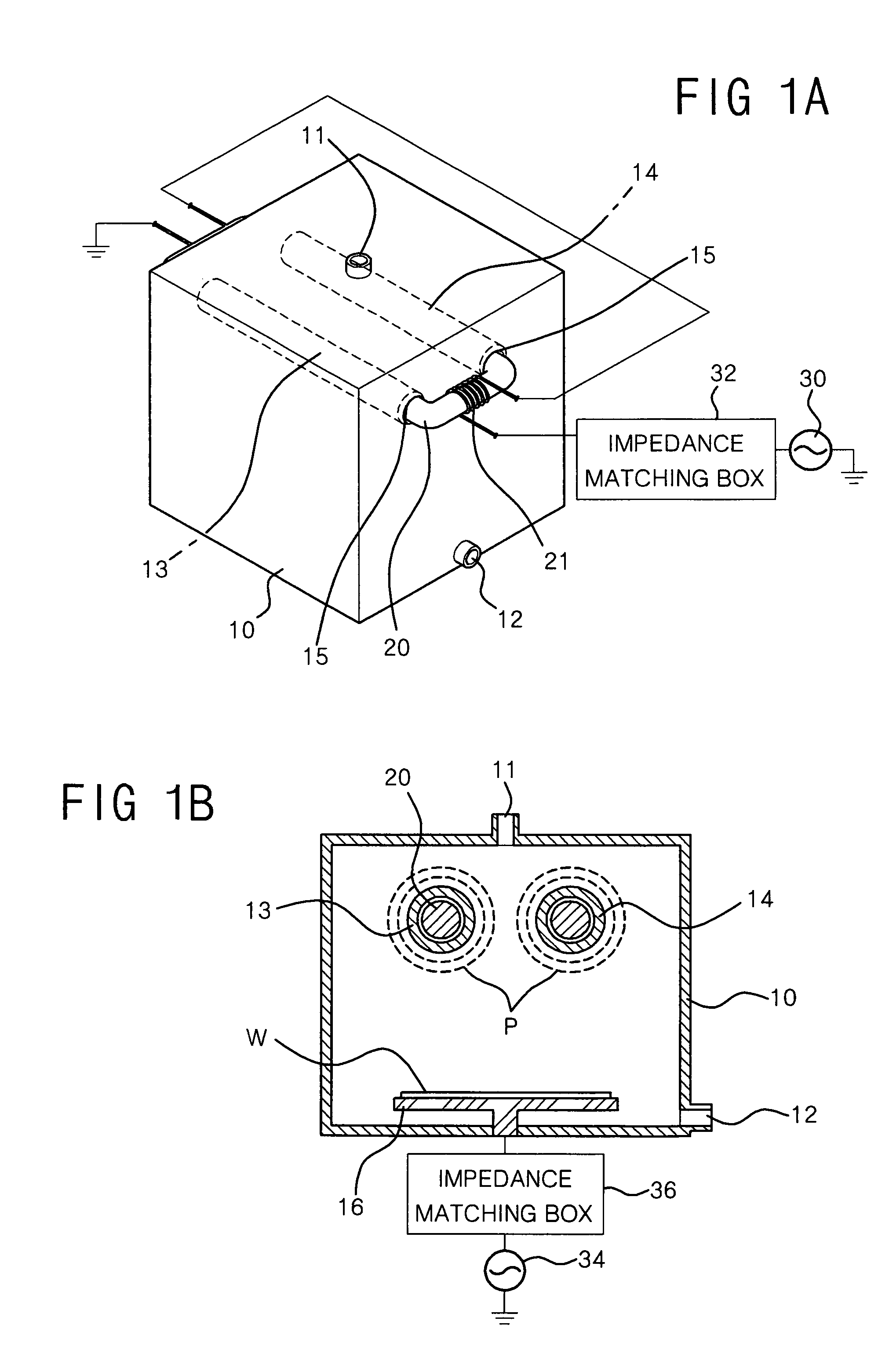
[0112]FIGS. 1A and 1B are a perspective view and a cross-sectional view, respectively, of a plasma processing chamber according to the first embodiment of the present invention.
[0113]Referring to FIGS. 1A and 1B, the plasma processing chamber includes chamber housing 10 and two discharge inducing bridges 13 and 14 positioned inside chamber housing 10. Discharge inducing bridges 13 and 14 are linear hollow tubes. Toroidal magnetic core 20 is mounted in discharge inducing bridges 13 and 14, and magnetic core 20 with winding coil 21 forms a transformer. Winding coil 21 is electrically connected to power supply source 30 supplying radio frequency to the primary winding of the transformer, through impedance matching box 30.
[0114]Chamber housing 10 includes a number of holes 15 formed in two sidewalls opposed to each other. Both ends of each of discharge inducing bridges 13 and 14 are connected to holes 15. A passage within chamber housing 10 from the outside of chamber housing 10 is prov...
embodiment ii
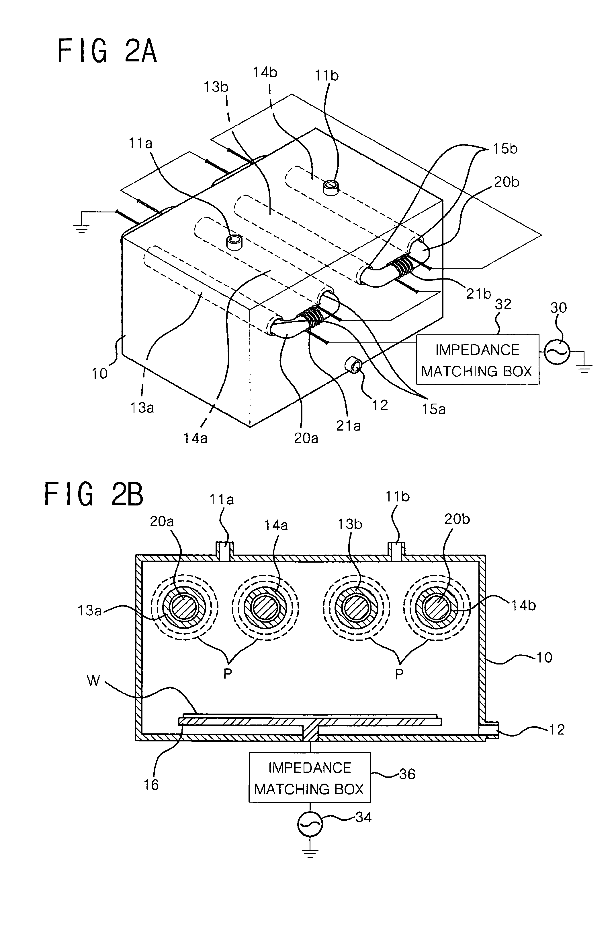
[0138]FIGS. 6A and 6B are a projection view and a cross-sectional view, respectively, of a plasma processing chamber according to a second embodiment of the present invention.
[0139]Referring to FIGS. 6A and 6B, the plasma processing chamber according to the second embodiment generates the inductive coupled plasma P in the same manner as the plasma processing chamber according to the first embodiment described above. Thus, a repeated description thereof will not be presented.
[0140]In the plasma processing chamber, two susceptors 540 are positioned at two sidewalls opposed to each other inside chamber housing 510. Two discharge inducing bridges 522 are horizontally positioned in a vertical plane and equally spaced apart from two susceptors 540. Magnetic core 520 with winding coil 520 is mounted in the discharge inducing bridges 522.
[0141]Gas entrance 511 is formed in the ceiling of chamber housing 510. The gas entrance 510 is preferably positioned above discharge inducing bridges 522,...
embodiment iii
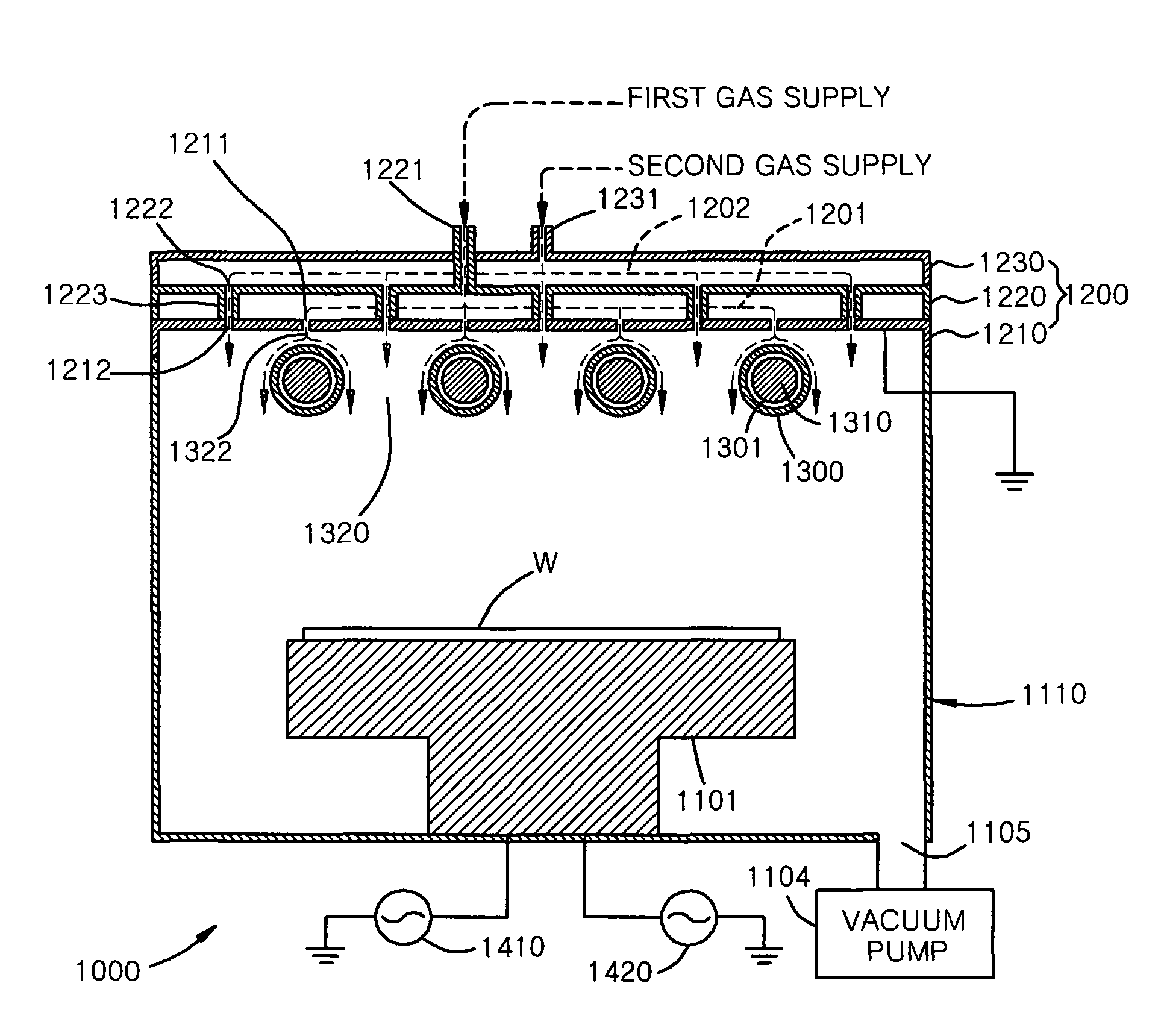
[0146]FIGS. 8A, 8B and 8C are a projection view, an exploded view and a cross-sectional view, respectively, of plasma processing chamber 1000 according to a third embodiment of the present invention.
[0147]Referring to FIGS. 8A, 8B and 8C, plasma processing chamber 1000 includes chamber housing 1110 having susceptor 1101 on which work substrate W is placed; and gas supply unit 1200 positioned on chamber housing 1110.
[0148]A plural number of discharge inducing bridges 1300 are horizontally positioned in a horizontal manner at an upper part of chamber housing 1110, from first sidewall 1111 of chamber housing 1110 to second sidewall 1112 opposed to first sidewall 1111, above susceptor 1101. Gas exit 1105 is positioned at a lower part of chamber housing 1110 and is connected to vacuum pump 1104.
[0149]Holes 1113 are formed in two sidewalls 1111 and 1112 of chamber housing 1110, from and to which discharge inducing bridges 1300 are connected. Holes 1113 receive both ends of each discharge ...
PUM
| Property | Measurement | Unit |
|---|---|---|
| electrical current | aaaaa | aaaaa |
| electrically insulating | aaaaa | aaaaa |
| magnetic | aaaaa | aaaaa |
Abstract
Description
Claims
Application Information
 - R&D
- Intellectual Property
- Life Sciences
- Materials
- Tech Scout
- Unparalleled Data Quality
- Higher Quality Content
- 60% Fewer Hallucinations
Browse by: Latest US Patents, China's latest patents, Technical Efficacy Thesaurus, Application Domain, Technology Topic, Popular Technical Reports.
© 2025 PatSnap. All rights reserved.Legal|Privacy policy|Modern Slavery Act Transparency Statement|Sitemap|About US| Contact US: help@patsnap.com


