Photonic crystal fiber sensor

a technology of photonic crystal fiber and sensor, applied in the direction of cladded optical fibre, optical radiation measurement, instruments, etc., can solve the problems of difficult to form nanowire coils having orientations, limited use of nanowire fiber, and time-consuming and/or expensive maintenance of detection devices that utilize irreversible chemical reactions

Inactive Publication Date: 2011-05-31
HONEYWELL INT INC
View PDF33 Cites 5 Cited by
  • Summary
  • Abstract
  • Description
  • Claims
  • Application Information

AI Technical Summary

Problems solved by technology

Detection devices that utilize irreversible chemical reactions are typically time consuming and / or expensive to maintain because at least a portion of the detection device needs to be replaced or steps need to be undertaken to reset the device if a quantity of the chemical or biological substance has been detected.
However, the use of nanowire fiber is limited because nanowire is typically very fragile.
It is also difficult to form nanowire coils having orientations other than a straight path due, in part, to the nanowire manufacturing process.
These limitations influence the type of platform capable of housing a device and the structures that can be utilized.
These limitations are compounded in a chemical or biological sensing device because the nanowire fiber needs to be exposed to the surrounding environment in order to interact with the substance to be detected.
In such a platform, it is difficult to ensure only light and substance interactions, without interference from its packaging environment since it needs to be supported.
Thus, the supporting environment severely compromises the measurement.
However, increasing the length of the nanowire leads to a device that is even more fragile.

Method used


Image

  • Photonic crystal fiber sensor
  • Photonic crystal fiber sensor
  • Photonic crystal fiber sensor

Examples


Embodiment Construction

[0019]An apparatus and method are provided for sensing one or more chemical or biological substances. Applicant hereby incorporates U.S. Pat. No. 7,336,859 and Published U.S. Patent Applications 2008 / 0212104 and 2008 / 0116361 in their entireties by reference.

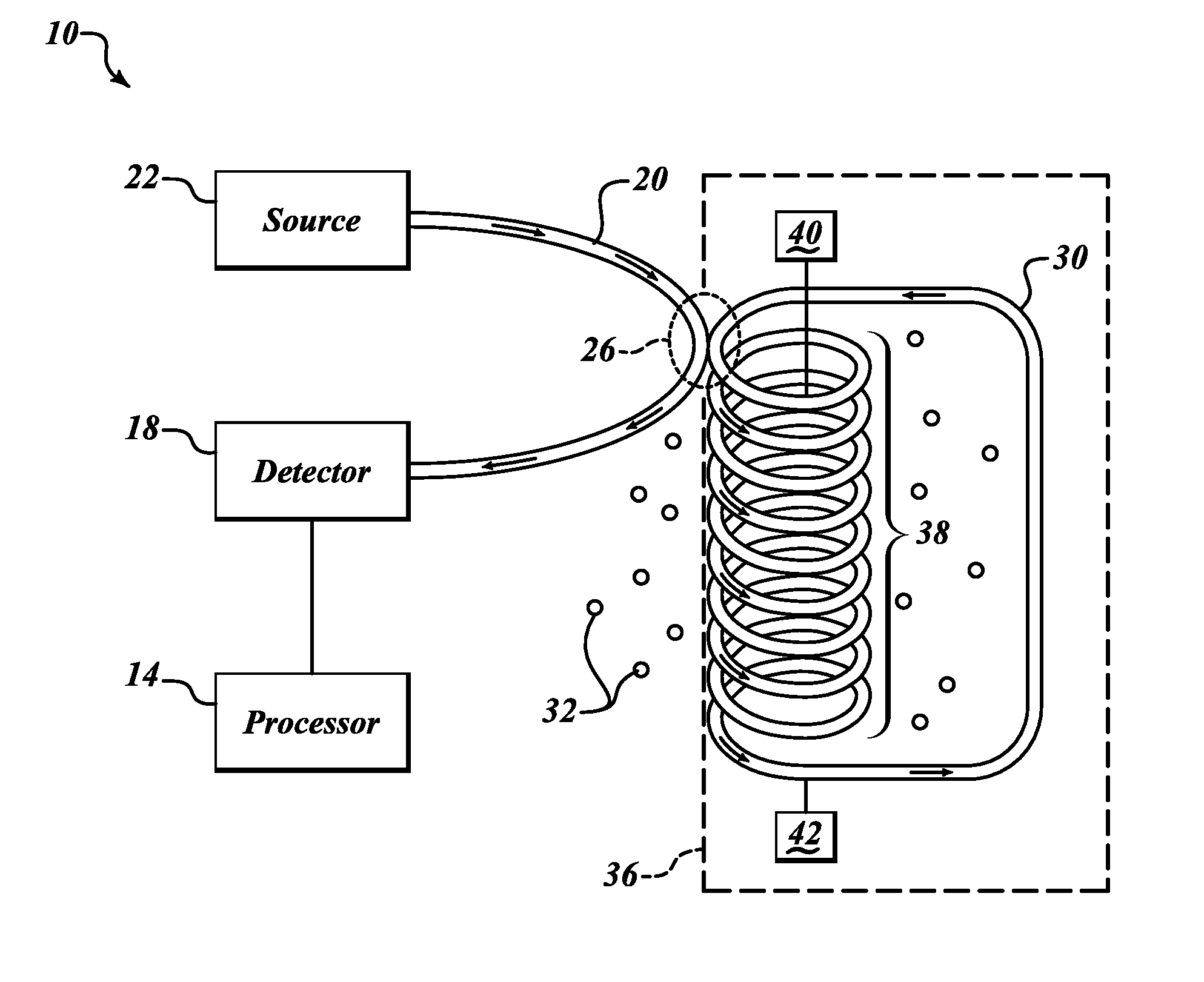
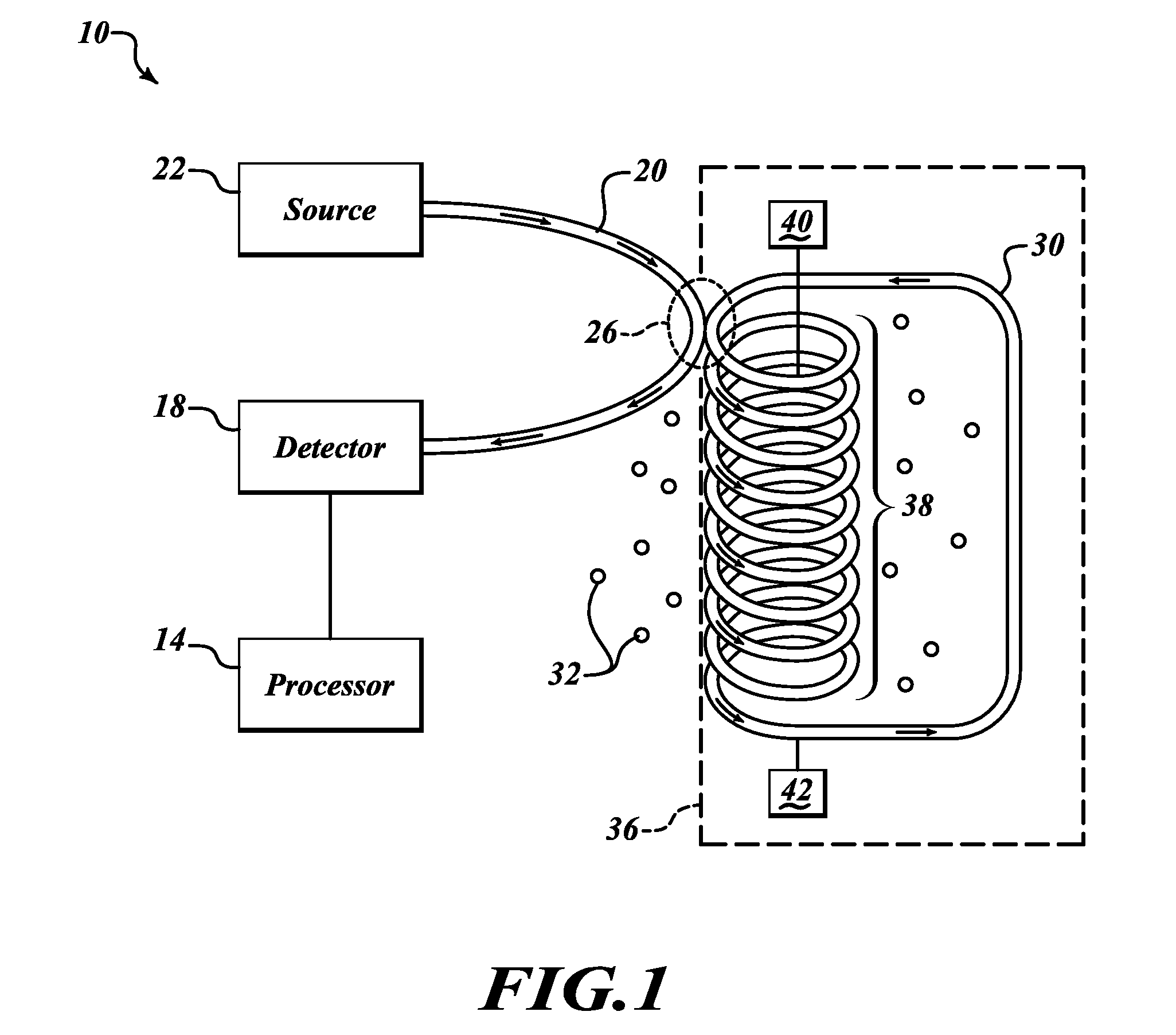
[0020]FIG. 1 shows an analyte sensor 10. As used herein, “analyte” means a specific chemical or biological substance sought to be detected. The analyte sensor 10 includes a detector 18, a light source 22, a first fiber 20, and a resonator 36. The light source 22 and the detector 18 are in optical communication via the first fiber 20. The first fiber 20 is also in optical communication with the resonator 36. An optical connection between the first fiber 20 and the resonator 36 is defined by a coupling junction 26.

[0021]The light source 22 includes a tunable monochromatic light source such as, but not limited to, a laser diode. In one embodiment, the light source 22 scans frequencies over a period of time. Accordingly, the frequenc...


PUM


Abstract

Apparatus and method for chemical and biological agent sensing. An example sensing apparatus includes a resonator having a resonance frequency. The resonator includes a coil of a photonic crystal fiber. The photonic crystal fiber has a solid region configured to guide a substantially single optical mode of light having, a cladding surrounding an exterior of the solid region, and at least one hollow core within the cladding. The cladding contains at least one hollow core. The photonic crystal fiber is configured to introduce a fluid that may contain an analyte to the hollow core. The photonic crystal fiber is configured so that the light interacts with the fluid. The resonator is configured to produce a resonance signal centered at the resonance frequency. A predetermined change in the resonance signal indicates a presence of a quantity of the analyte in the fluid.

Description

BACKGROUND OF THE INVENTION[0001]The presence of a chemical or biological substance has traditionally been detected by utilizing one or more chemical reactions. These chemical reactions are usually irreversible, i. e. the reactions are not reset if the chemical or biological substance is removed from the device. Detection devices that utilize irreversible chemical reactions are typically time consuming and / or expensive to maintain because at least a portion of the detection device needs to be replaced or steps need to be undertaken to reset the device if a quantity of the chemical or biological substance has been detected.[0002]Alternatively, a detection device may be reversible, i.e. the device can be reset automatically if a detected chemical or biological substance is removed. Thus, a reversible device is usually reusable. One type of reversible detection device uses a physics-based, spectroscopic solution to determine the presence of a substance without a chemical reaction. Spec...

Claims


Application Information

Patent Timeline
Patent Type & Authority Patents(United States)
IPC IPC(8): G01B9/02G02B6/00
CPCG01N21/7746G02B6/02385G01N21/39G01N2021/7789G02B6/02366G01N2021/7766
Inventor SANDERS, GLEN A.
Owner HONEYWELL INT INC
Why Eureka
Try Eureka