Optical fiber, optical fiber amplifier, and optical fiber laser light source

a technology of optical fiber and laser light source, which is applied in the field of optical fiber, can solve the problems of inefficiency in using the energy of the pump lightwave inability to excite metallic ions efficiently, and achieve the effect of efficient excitation of metallic ions

Inactive Publication Date: 2008-04-22
SUMITOMO ELECTRIC IND LTD
View PDF10 Cites 4 Cited by
  • Summary
  • Abstract
  • Description
  • Claims
  • Application Information

AI Technical Summary

Benefits of technology

[0007]An object of the present invention is to offer an optical fiber capable of efficiently exciting metallic ions and to offer an optical fiber amplifier and an optical fiber laser light source both incorporating the optical fiber.

Problems solved by technology

Therefore, in the case of a pump lightwave travelling in a mode having no intensity peak in the core region, the metallic ions cannot be excited.
In other words, the energy of the pump lightwave cannot be used efficiently to excite the metallic ions.

Method used


Image

  • Optical fiber, optical fiber amplifier, and optical fiber laser light source
  • Optical fiber, optical fiber amplifier, and optical fiber laser light source
  • Optical fiber, optical fiber amplifier, and optical fiber laser light source

Examples


first embodiment

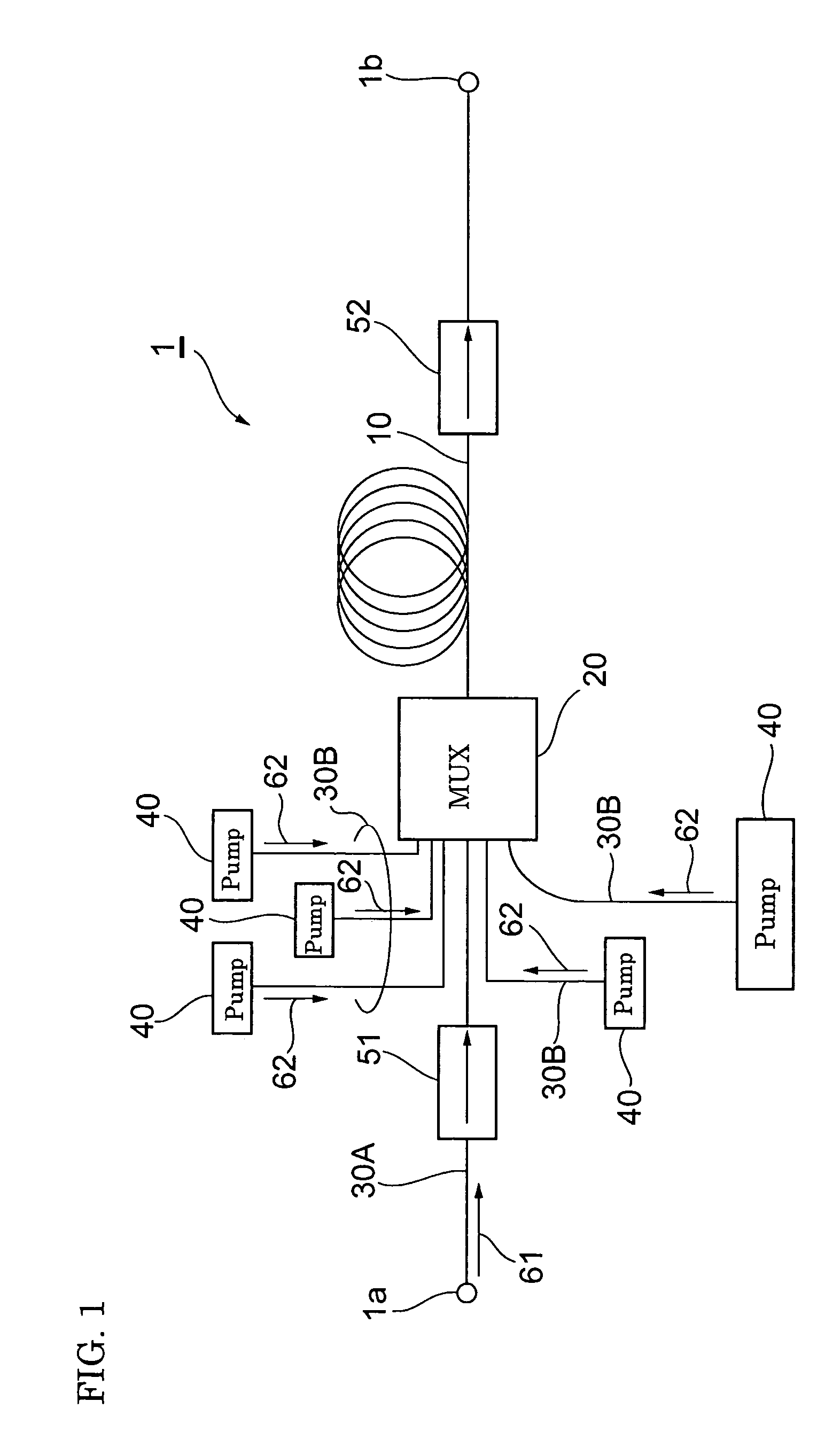
[0030]FIG. 1 is a conceptual diagram showing a first embodiment of an optical fiber amplifier of the present invention. An optical fiber amplifier 1 that optically amplifies a signal lightwave by being supplied with a pump lightwave has (a) an optical fiber 10, (b) light source sections 40 for outputting pump lightwaves, (c) a light-supplying means (multiplexer 20) for supplying the pump lightwaves and a signal lightwave to the optical fiber, (d) connection-use optical fibers 30A and 30B, and (e) isolators 51 and 52 provided for the optical fibers 30A and 10, respectively. The optical fiber amplifier 1 optically amplifies a signal lightwave 61 inputted from an input end 1a to output it from an output end 1b. The provision of the isolators 51 and 52 prevents light from travelling from the output-end-1b side toward the input-end-1a side. The foregoing optical fiber amplifier 1 is used in an optical communication system, for example.

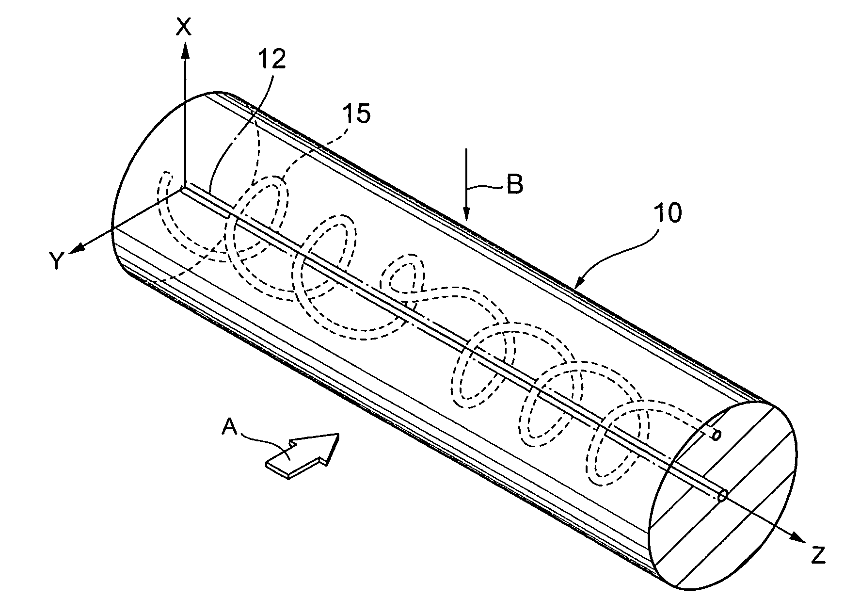
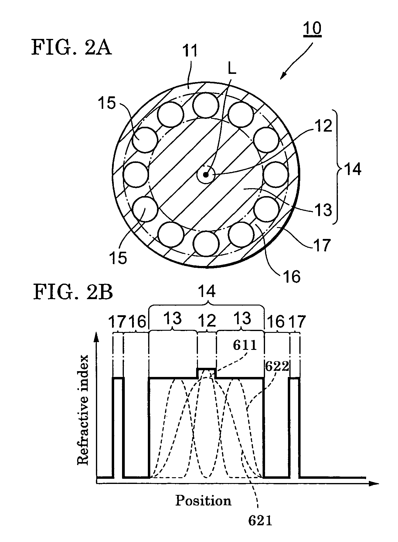
[0031]The optical fiber 10 is a linear body composed ...

second embodiment

[0052]FIG. 9 is a conceptual diagram showing a second embodiment of an optical fiber amplifier of the present invention. An amplifier 2 has an optical fiber 10 having a total length of, for example, 39 meters and a pump light source section 41 optically coupled with an end 10a of the optical fiber 10. The pump light source section 41 outputs a pump lightwave 62 having a wavelength of λ2 capable of exciting Er3+ contained in the optical fiber 10. The pump light source section 41 is composed of, for example, a group of semi-conductor laser devices and outputs the pump lightwave 62 at an intensity of 0.5 kW. The pump light source section 41 may also be composed of one semi-conductor laser device.

[0053]A pair of lenses 101A and 101B are placed between the pump light source section 41 and the end 10a. A dichroic mirror 111 is placed between the lenses 101A and 101B. In the dichroic mirror 111, a film composed of multiple dielectric layers is formed that has high transmittance for the pum...

third embodiment

[0062]FIG. 10 is a conceptual diagram showing an embodiment of an optical fiber laser light source of the present invention. An optical fiber laser light source 3 has an optical fiber 120 whose structure differs from that of the optical fiber 10 in that Yb3+ is doped in the core region 12 in place of Er3+ as the metallic ion for the optical amplification. The optical fiber 120 has a total length of, for example, 23 meters. The amount of the Yb3+ doped in the core region 12 is 600 wt. ppm. The core region 12 has a diameter of about 20 μm. A value of 0.06 is achieved as the NA for the light having a wavelength of λ3 emitted from the Yb3+. The wavelength λ3 of the light emitted from the Yb3+ is, for example, about 1.06 μm.

[0063]In order to excite the Yb3+ doped in the core region 12 of the optical fiber 120, the optical fiber laser light source 3 has a light source section 130 for outputting a pump lightwave 63 having a wavelength of λ4 capable of exciting the Yb3+. The light source se...


PUM

PropertyMeasurementUnit
total lengthaaaaaaaaaa
diameteraaaaaaaaaa
diameteraaaaaaaaaa

Abstract

An optical fiber can efficiently excite metallic ions by a pump lightwave, and an optical fiber amplifier and an optical fiber laser light source both incorporate the optical fiber. The optical fiber comprises (a) a solid region that has a first region doped with metallic ions and a second region surrounding the first region and that allows a lightwave for exciting the metallic ions to travel in a multiple mode and (b) a third region surrounding the second region and having a plurality of holes stretching along the length of the optical fiber. The optical fiber has a structure in which the first region is supplied with the power of a lightwave that is included in the pump lightwave and that is in a mode having no intensity peak at the center axis of the solid region.

Description

BACKGROUND OF THE INVENTION[0001]1. Field of the Invention[0002]The present invention relates to an optical fiber and to an optical fiber amplifier and an optical fiber laser light source both incorporating the optical fiber.[0003]2. Description of the Background Art[0004]An optical fiber amplifier and an optical fiber laser light source sometimes incorporate a double-cladding-type optical fiber as the amplification medium. This optical fiber is composed of (a) a core region doped with metallic ions that are excited when a pump lightwave is supplied, (b) a first cladding region surrounding the core region, and (c) a second cladding region further surrounding the first cladding region. A solid region composed of the core region and the first cladding region guides the pump lightwave, and the core region guides a signal lightwave. Because the metallic ions are excited by the pump lightwave, when a signal lightwave travels in the core region, the metallic ions emit stimulated-emission ...

Claims


Application Information

Patent Timeline
Patent Type & Authority Patents(United States)
IPC IPC(8): G02B6/02C03B37/012G02B6/036H01S3/067H01S3/094H01S3/16
CPCC03B37/01211C03B37/01231C03B37/02745G02B6/02366G02B6/03672C03B2201/31C03B2201/34C03B2201/36C03B2203/14C03B2203/18C03B2203/19C03B2203/22C03B2203/32C03B2205/06C03B2205/10G02B6/03605H01S3/06708H01S3/06741H01S3/094003H01S3/094007H01S3/1608H01S3/1691H01S3/1693H01S3/1698G02B6/02H01S3/067H01S3/06754
Inventor KATAYAMA, TETSUTAROISHIKAWA, SHINJI
Owner SUMITOMO ELECTRIC IND LTD
Why Eureka
Try Eureka