[0007]The object of the invention is to improve the effectiveness of the
water supply systems of shearer loaders.
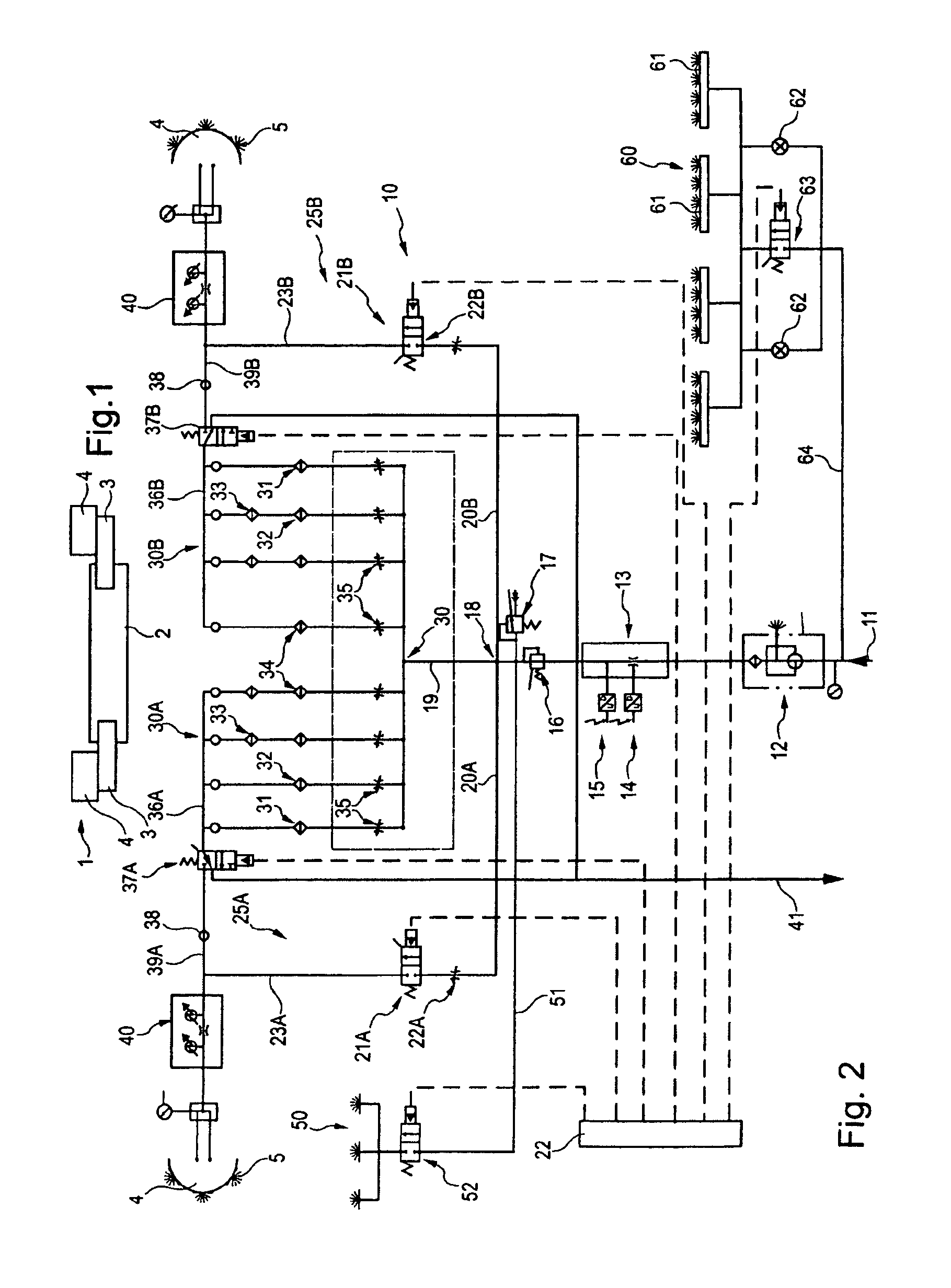
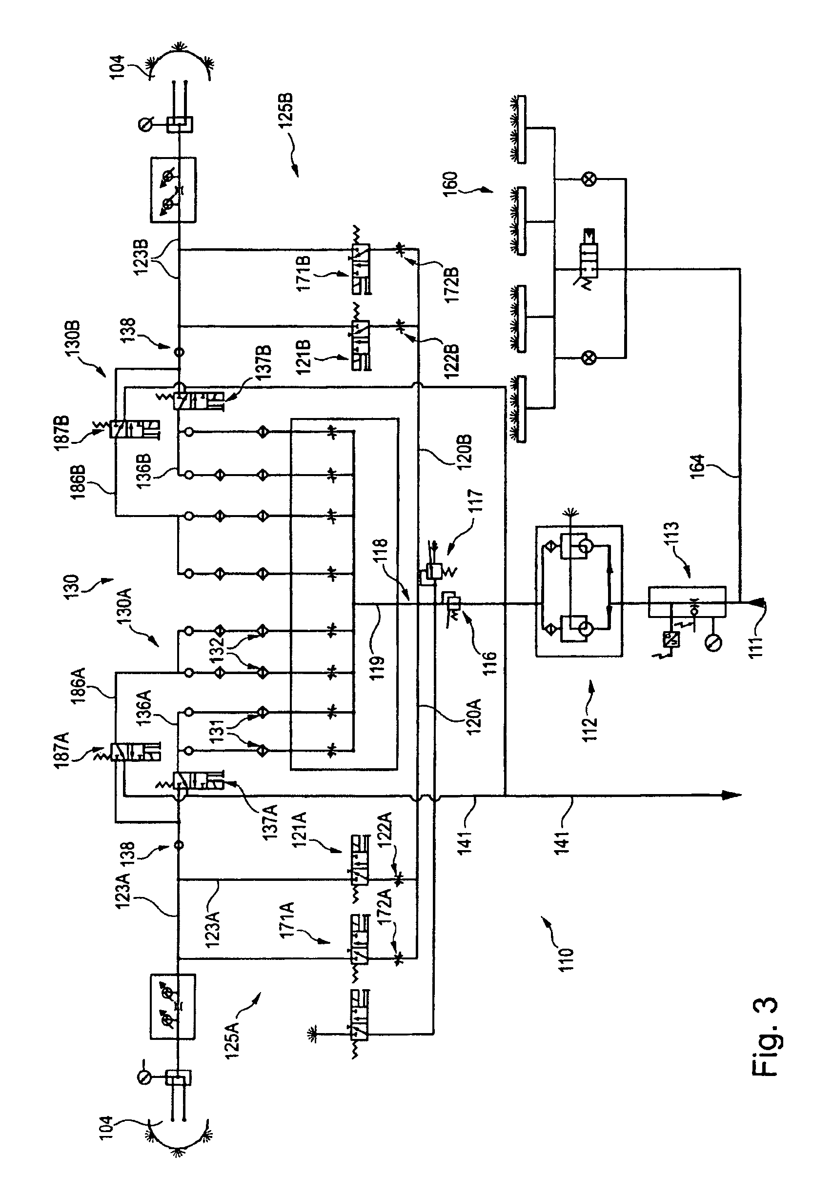
[0008]To achieve this and other objects, it is proposed according to the invention that, in shearer loaders of the generic type, a respective control valve connected to one of the feed lines be arranged in return lines of the cooling water circuit, via which control valve the cooling water can be fed as spray water to the cutting drums as and when required. In the shearer loader according to the invention, the cooling water can therefore be fed, as and when required, to the spray nozzles at the cutting drums by opening the
control valves and can be used there as spray water. An effective spray
water supply which can be adapted to the respective ventilating conditions and mining conditions can therefore be provided at an overall lower requisite
water flow rate for the shearer loader. Since the cooling water is fed to the cutting drums only as and when required, floor lift can at the same time be avoided to the greatest possible extent and it is no longer necessary to pump excess spray water away from the longwall.
[0011]A pressure limiting valve and / or a pressure regulating valve is expediently arranged downstream of the water connection in the common water feed to both water circuits in order to detect or avoid malfunctions due to the
water volume, possibly established by the mines, and the
water pressure for the spraying exceeding or falling below the threshold values. For example, in the event of a
water supply that is too low, a
limit value in relation to dust protection could be exceeded, for which reason the winning
machine should be switched off or reduced in its output if this
hazard situation is detected. Exceeding or falling below a threshold value may at the same time indicate obstruction of the nozzles or other malfunctions. In order to reliably detect this, it is also expedient if a volumetric flow sensor is arranged upstream of the pressure limiting valve. In order to avoid
contamination of the circuits and clogging of the nozzles, it is also advantageous if a
water filter, preferably a reversible flow filter, is arranged in the water feed upstream of the volumetric flow sensor. Furthermore, it is expedient if a
branch point is formed downstream of the pressure limiting valve, said
branch point opening with one
branch into the cooling water circuit and with one or preferably two branch lines into separate spray water circuits for the individual cutting drums.
[0012]In a preferred configuration, the spray system has a first spray water circuit for the one cutting drum and a separate second spray water system for the other cutting drum, wherein the cooling water can be fed or is fed to the cutting drums, via the one respective or via the at least one respective control valve connected to the feed lines, as an additional volume of spray water with
control valves open and valves open or solely as spray water with valves closed and
control valves open. By the division of the fed water into separate spray water circuits for both cutting drums and by connecting the water from the cooling water circuits to the system as and when required, considerably more effective spraying optimized with regard to
water consumption control can be realized. It may suffice to arrange in each case precisely one valve and one control valve for each sub-circuit in the spray water circuit and / or in the cooling water circuit in order to be able to carry out the spraying optionally only with cooling water, only with spray water or with the volumetric flows of cooling water and spray water.
[0013]According to a further configuration, at least two valves which can be activated independently of one another can be arranged between the water connection, in particular between the associated
branch line of the spray water sub-circuit, and the respective feed line in the spray water circuit for each cutting drum, and / or at least two control valves which can be activated independently of one another can be arranged for each cutting drum between the return line and the respective feed line to the cutting drum in the cooling water circuit. By separate activation of the respective control valves and valves, not only can the volume of water for the spraying then actually fed to the cutting drums be set differently for the individual cutting drums, but the volume can also be adapted gradually to the requirements, with little outlay in terms of circuitry, in order to spray only the
water volume required for
dust control at the longwall, while the rest of the water is directed away from the longwall again via the return lines and a return hose. For further optimization and improvement in effectiveness, a volume regulating valve can be assigned to each valve in the spray water circuit.
[0014]Furthermore, in order to increase safety at the longwall, a branch to an extinguishing spray system which can preferably be switched on manually can preferably be arranged in the water circuit. Alternatively or additionally, a branch leading into a camera cleaning system which can be switched on and off and is intended for cleaning, for example, a monitoring camera for the longwall or the shearer loader can be arranged downstream of the pressure limiting valve.

