Density and viscosity sensor

a density and viscosity sensor and density sensor technology, applied in the direction of instruments, specific gravity measurement, measurement devices, etc., can solve the problems of high cost, high intrusive measurement device, and difficult operation at high pressure and high temperature, so as to avoid fluid flow perturbation, high strength, and corrosion resistance alloys high

Active Publication Date: 2011-06-14
SCHLUMBERGER TECH CORP
View PDF5 Cites 26 Cited by
  • Summary
  • Abstract
  • Description
  • Claims
  • Application Information

AI Technical Summary

Benefits of technology

[0008]According to a first aspect of the invention, the excitation-detection scheme of the present sensor is based on the transfer of a mechanical signal through a membrane having on one side an actuating / detecting element isolated from the fluid and on the other side a resonating element immersed in the fluid. More precisely, the density and viscosity sensor of the invention comprises a resonating element arranged to be immersed in the fluid, an actuating / detecting element coupled to the resonating element, and a connector for coupling to the actuating / detecting element. The sensor further comprises a housing defining a chamber isolated from the fluid, the housing comprising an area of reduced thickness defining a membrane separating the chamber from the fluid. The actuating / detecting element is positioned within the chamber so as to be isolated from the fluid and mechanically coupled to the membrane. The resonating element arranged to be immersed in the fluid, is mechanically coupled to the membrane. The membrane has a thickness enabling pressure resistance and transfer of mechanical vibration between the actuating / detecting element and the resonating element. The resulting membrane stiffness enables decoupling the resonating element properties from the actuating / detecting element.
[0009]More precisely, the density and viscosity sensor according to the invention comprises a resonating element arranged to be immersed in the fluid, an actuating / detecting element coupled to the resonating element, and a connector for coupling to the actuating / detecting element. The sensor further comprises a housing defining a chamber isolated from the fluid, the housing comprising an area of reduced thickness defining a membrane separating the chamber from the fluid. The actuating / detecting element is positioned within the chamber so as to be isolated from the fluid and mechanically coupled to the membrane. The resonating element arranged to be immersed in the fluid is mechanically coupled to the membrane. The membrane has a thickness enabling transfer of mechanical vibration between the actuating / detecting element and the resonating element.
[0023]According to a second aspect of the invention, the method for measuring density and viscosity of a fluid is based on a particular excitation-detection scheme. The excitation-detection scheme is based on an elementary sequence comprising three phases: an excitation phase, a waiting phase and a detection phase. During the excitation phase, an excitation signal of an initial frequency constituted by M periods is applied to the actuating / detecting element (for example M is equal to 4). The waiting phase has a duration of N periods (for example N is equal to 1). The detection phase has a duration of P periods (for example P is equal to 3). The elementary sequence is repeated K times (for example K is of the order of the quality factor Q) for the initial frequency, thus enabling the determination of a measured or actual in-phase spectral component and a measured or actual quadrature spectral component.
[0043]The sensor design allows a minimal intrusion in the fluid flow line to be measured, thus avoiding fluid flow perturbations, erosion issues, potential plugging and ensuring sensor reliability over a long period of time.
[0045]Also, as there is no electrical feed-through between the resonating element and the actuating / detecting element, the sensor housing can be made of a simple and robust monolithic block. Thus, temperature induced stress effects are reduced. The sensor can be miniaturized with regards to prior art sensor and well adapted for harsh environment applications. It is also well adapted to be manufactured at low cost.
[0046]Finally, the measurement method of the invention allows a drastic reduction of the background offsets and noise. This greatly improves the operating range of the sensor and the density / viscosity predictions robustness and accuracy.

Problems solved by technology

This transducer has a typical size of several centimeters requiring a bulky and expensive sensor housing.
This leads to a highly intrusive measuring device preventing its use in small sample chambers or small pipes.
Further, operation at high pressure and high temperature is also very difficult to implement due to the large size.

Method used


Image

  • Density and viscosity sensor
  • Density and viscosity sensor
  • Density and viscosity sensor

Examples


first embodiment

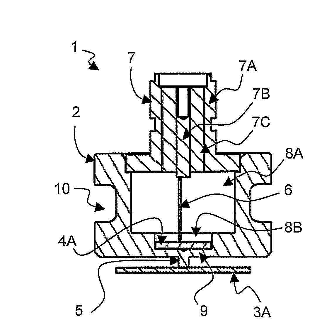
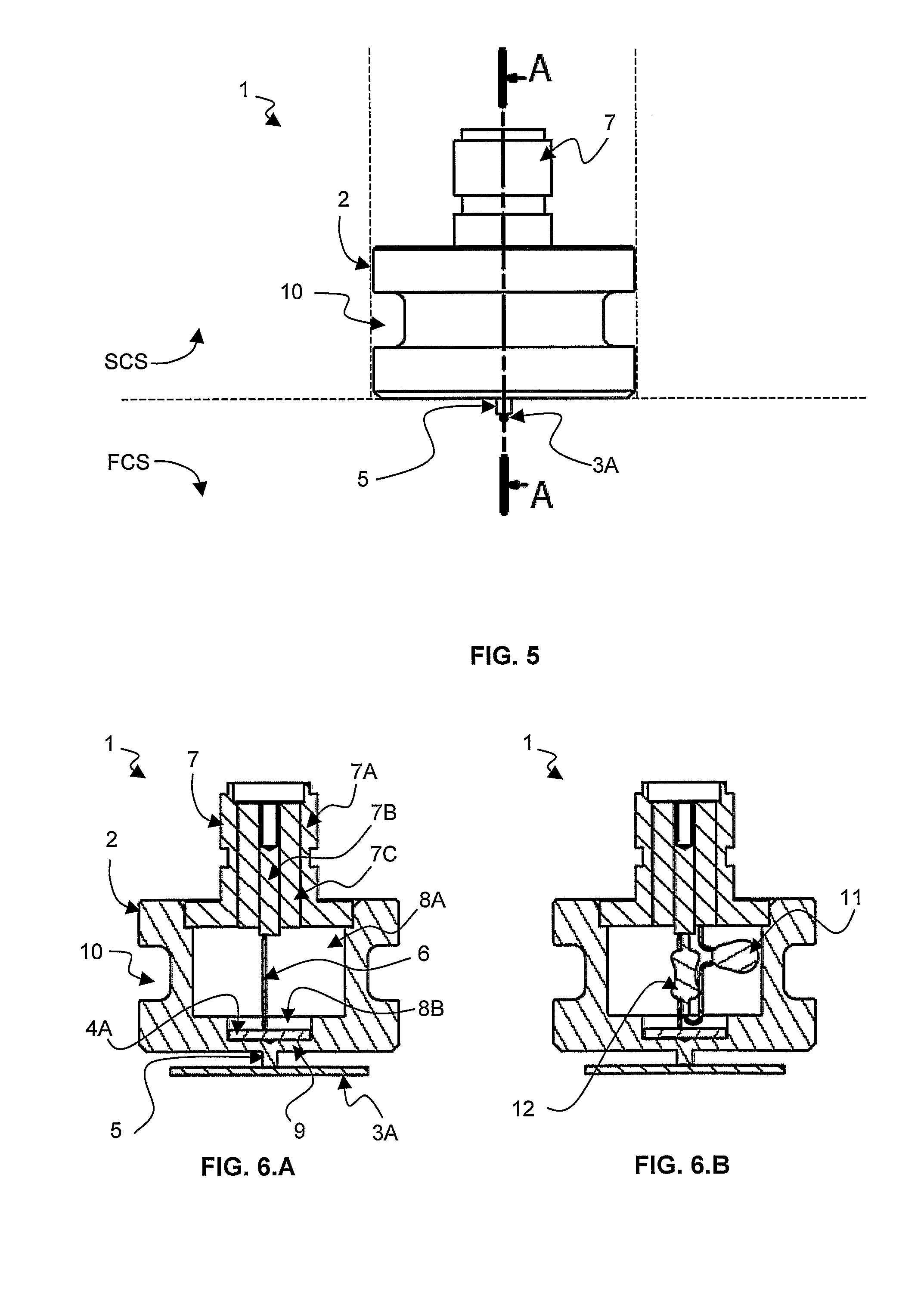
[0067]FIG. 6.A is a cross-section view in a sensor 1 according to a first alternative of the The housing comprises a housing interior part defining a chamber 8A. The housing 2, in the chamber side, comprises a cavity 8B. The cavity 8B defines an area where the housing has a reduced thickness defining a membrane 9 between the chamber 8A and the fluid contacting side FCS. The coupling element 5 is positioned onto the membrane 9. Preferably, the coupling element 5 is positioned at sensibly a center point on the membrane. The chamber 8A may be filled with a material. Advantageously, the material is a vibration absorbing material (e.g. gas, oil, gel, etc. . . . ). The vibration absorbing material enables to reduce perturbation due to parasitic vibration modes of the housing itself. The chamber 8A may be sealed via the connector 7.

[0068]An actuating / detecting element 4, for example a piezoelectric element 4A is positioned in the cavity 8B. One side of the piezoelectric element is coupled...

second embodiment

[0078]FIGS. 8.A, 8.B and 8.C are side, bottom and perspective bottom views schematically showing a density and viscosity sensor 1 according to the invention, respectively.

[0079]According to this embodiment the resonating element 3B is under the form of a single part beam attached at one end of the beam to the coupling element 5.

third embodiment

[0080]FIGS. 9.A, 9.B and 9.C are side, bottom and perspective bottom views schematically showing a density and viscosity sensor 1 according to the invention, respectively.

[0081]According to this embodiment the resonating element 3C is under the form of a non-symmetrical U beam. The beam may be a wire having e.g. a cylindrical cross-section or an elliptical cross-section and a diameter of a few micrometers. The wire comprises a first longitudinal part contacting the fluid to be measured. The wire comprises a second bent part which is attached by one end to the coupling element 5.

[0082]Preferably, the beam according to the first, the second and the third embodiment is aligned with the fluid flow. This configuration enables to minimize erosion effect in high velocity particles fluid. It also enables to minimize turbulences induced by the presence of the measuring device and thus the noise on the beam.


PUM

PropertyMeasurementUnit
densityaaaaaaaaaa
densityaaaaaaaaaa
angleaaaaaaaaaa

Abstract

A density and viscosity sensor 1 for measuring density and viscosity of fluid F, the sensor 1 comprising a resonating element 3, 3A, 3B, 3C, 3D arranged to be immersed in the fluid F, an actuating / detecting element 4A, 4B coupled to the resonating element, and a connector 7 for coupling to the actuating / detecting element 4A, 4B. The sensor 1 further comprises a housing 2 defining a chamber 8A isolated from the fluid F, the housing 2 comprising an area of reduced thickness defining a membrane 9 separating the chamber 8A from the fluid F. The actuating / detecting element 4A, 4B is positioned within the chamber so as to be isolated from the fluid F and mechanically coupled to the membrane 9. The resonating element 3, 3A, 3B, 3C, 3D arranged to be immersed in the fluid F is mechanically coupled to the membrane 9. The membrane 9 has a thickness enabling transfer of mechanical vibration between the actuating / detecting element 4A, 4B and the resonating element 3, 3A, 3B, 3C, 3D.

Description

FIELD OF THE INVENTION[0001]The invention relates to a sensor for measuring density and viscosity of a fluid. The sensor is based on the use of mechanical elements put into vibration in the fluid to be measured.[0002]The invention is applicable to density and viscosity measurements in the oilfield industry, in the chemical industry, in the food industry, etc. . . .BACKGROUND OF THE INVENTION[0003]The density is a measure of a mediums mass per unit of volume. The SI unit of density is the kilogram per cubic meter (kg / m3). As examples, at standard temperature and pressure condition, the density of water is 1000 kg / m3, of ethyl alcohol is 790 kg / m3, respectively.[0004]Viscosity is a measure of the resistance of a fluid to deformation under shear stress. Viscosity describes a fluid internal resistance to flow and may be thought of as a measure of fluid friction. The SI physical unit of dynamic viscosity is the Pascal second (Pa·s). The cgs physical unit for dynamic viscosity is the pois...

Claims


Application Information

Patent Timeline
Patent Type & Authority Patents(United States)
IPC IPC(8): G01N11/16G01N9/34
CPCG01N11/16G01N9/002
Inventor PERMUY, ALFREDDONZIER, ERIC
Owner SCHLUMBERGER TECH CORP
Why Eureka
Try Eureka