Open loop Brayton cycle for EGR cooling

a brayton cycle and open loop technology, applied in special engines, machines/engines, transportation and packaging, etc., can solve the problems of limiting the generation of harmful emissions, nitrogen oxides, increasing the demands on the engine's cooling system, etc., to reduce the cooling system capacity, reduce the amount of heat rejection, and reduce the temperature of exhaust gas

Active Publication Date: 2011-06-14
CUMMINS INC
View PDF20 Cites 41 Cited by
  • Summary
  • Abstract
  • Description
  • Claims
  • Application Information

AI Technical Summary

Benefits of technology

[0004]The present invention provides a system for reducing the temperature of exhaust gas in an exhaust gas recirculation loop of a vehicle's engine. In one embodiment, the system includes an air-air EGR cooler having a first flow path through which exhaust gas from the vehicle engine passes during movement through the exhaust gas recirculation loop, and a second flow path having an inlet and an outlet. A compressor is configured to compress ambient air and provide the compressed air to the inlet of the second flow path. The compressed air flowing through the second flow path draws heat from the exhaust gas flowing through the first flow path. A turbine coupled to the compressor by a shaft is configured to receive and expand the heated compressed air from the outlet of the second flow path, thereby causing rotation of the shaft and powering operation of the compressor.
[0005]In some applications of the present invention wherein the waste heat source is from a vehicle engine, cooling system capacity may be reduced. More specifically, recovery of waste heat energy and its conversion to useful work may serve to reduce the amount of heat rejection from that engine system by the amount of energy recovered and usefully converted. Also, cooling methods such as the present invention which utilize other waste heat rejection streams apart from the traditional radiator in-vehicle serve to benefit overall vehicle design by limiting the amount of frontal, cross-sectional area devoted to ‘ram-air’ cooling techniques and provide the vehicle designer with greater flexibility towards improving vehicle aerodymanic drag, thereby also improving overall vehicle fuel efficiency.

Problems solved by technology

This recirculated exhaust gas is mixed with incoming fresh air, and lowers the peak combustion temperature, thereby limiting the generation of harmful emissions, such as nitrogen oxides.
However, the high temperature exhaust gas recirculated to the engine increases the temperature of the incoming mix, and therefore increases the demands on the engine's cooling system.
This increased demand for heat rejection may require a larger radiator.
In vehicular engine systems where space is limited, increasing the size of the radiator is a difficult engineering challenge.

Method used


Image

  • Open loop Brayton cycle for EGR cooling
  • Open loop Brayton cycle for EGR cooling
  • Open loop Brayton cycle for EGR cooling

Examples


Embodiment Construction

[0011]For the purposes of promoting an understanding of the principles of the invention, reference will now be made to the embodiments illustrated in the drawings, which are described below. It will nevertheless be understood that no limitation of the scope of the invention is thereby intended. The invention includes any alterations and further modifications in the illustrated device and described method and further applications of the principles of the invention, which would normally occur to one skilled in the art to which the invention relates. Moreover, the embodiments were selected for description to enable one of ordinary skill in the art to practice the invention.

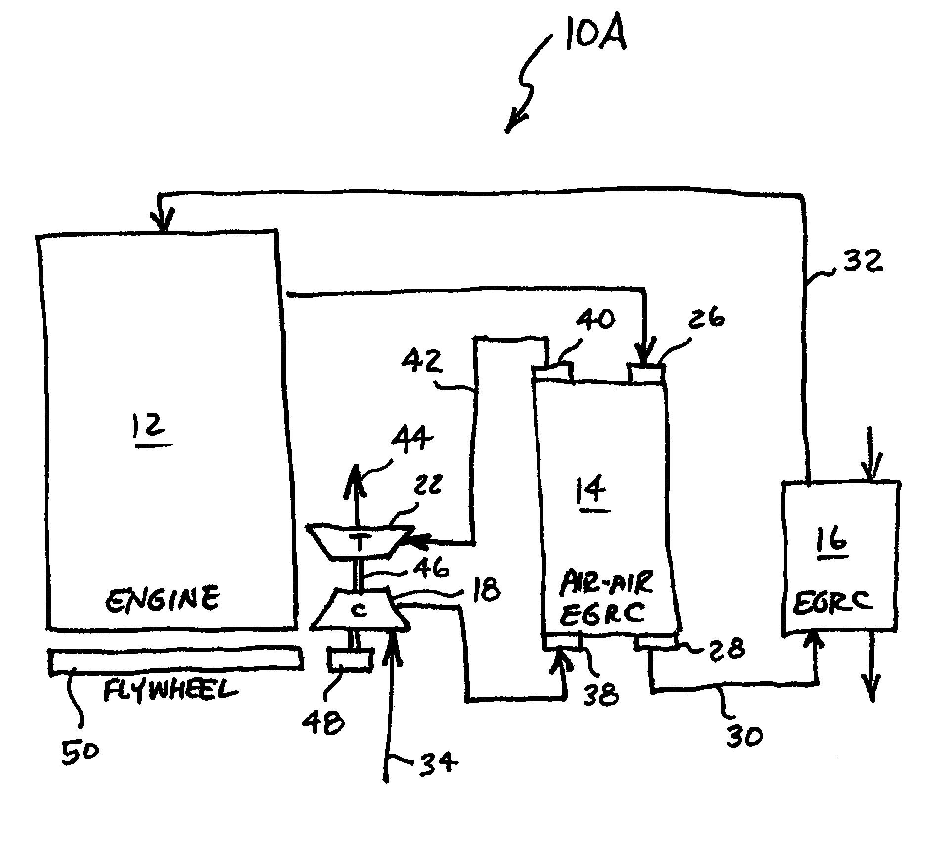
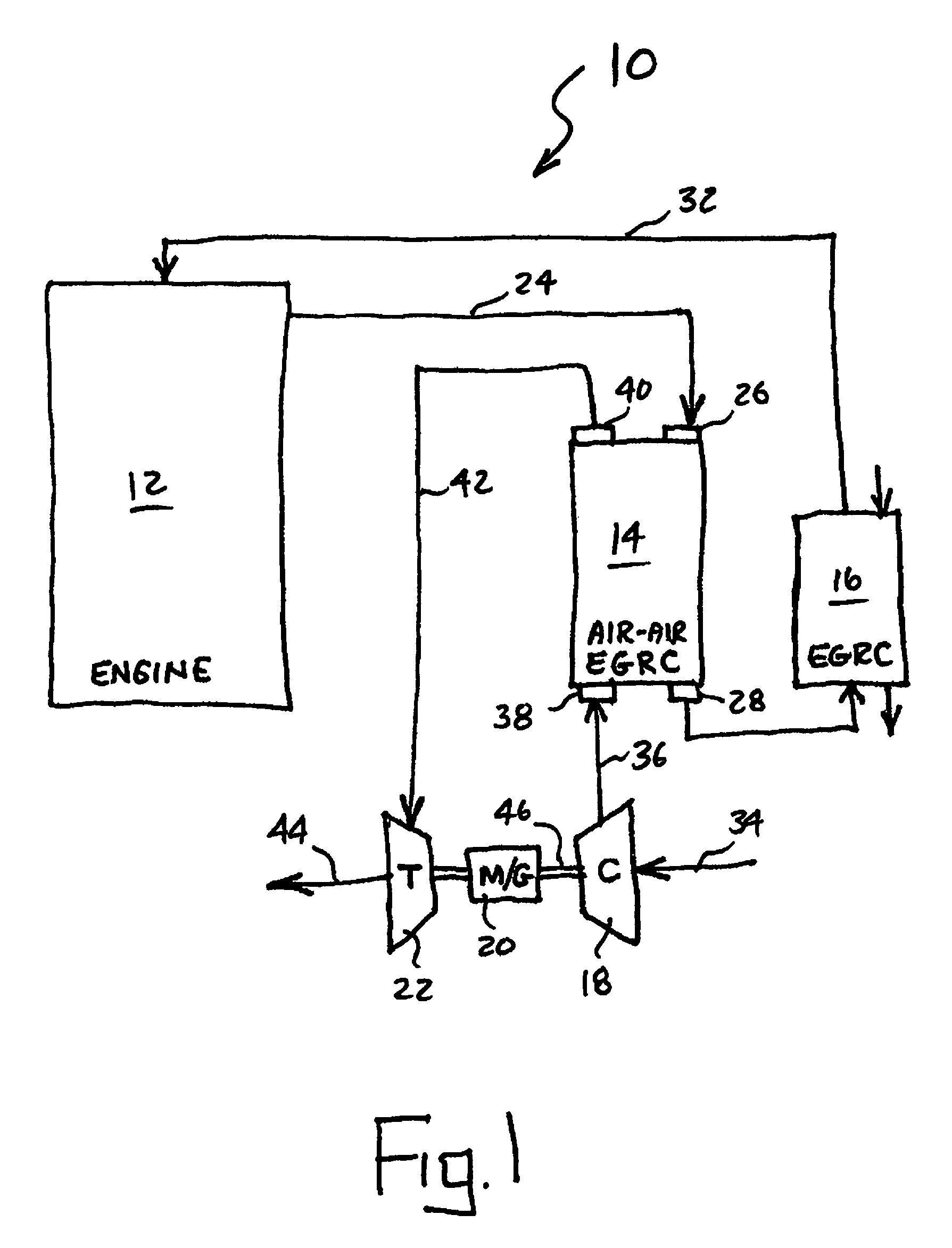
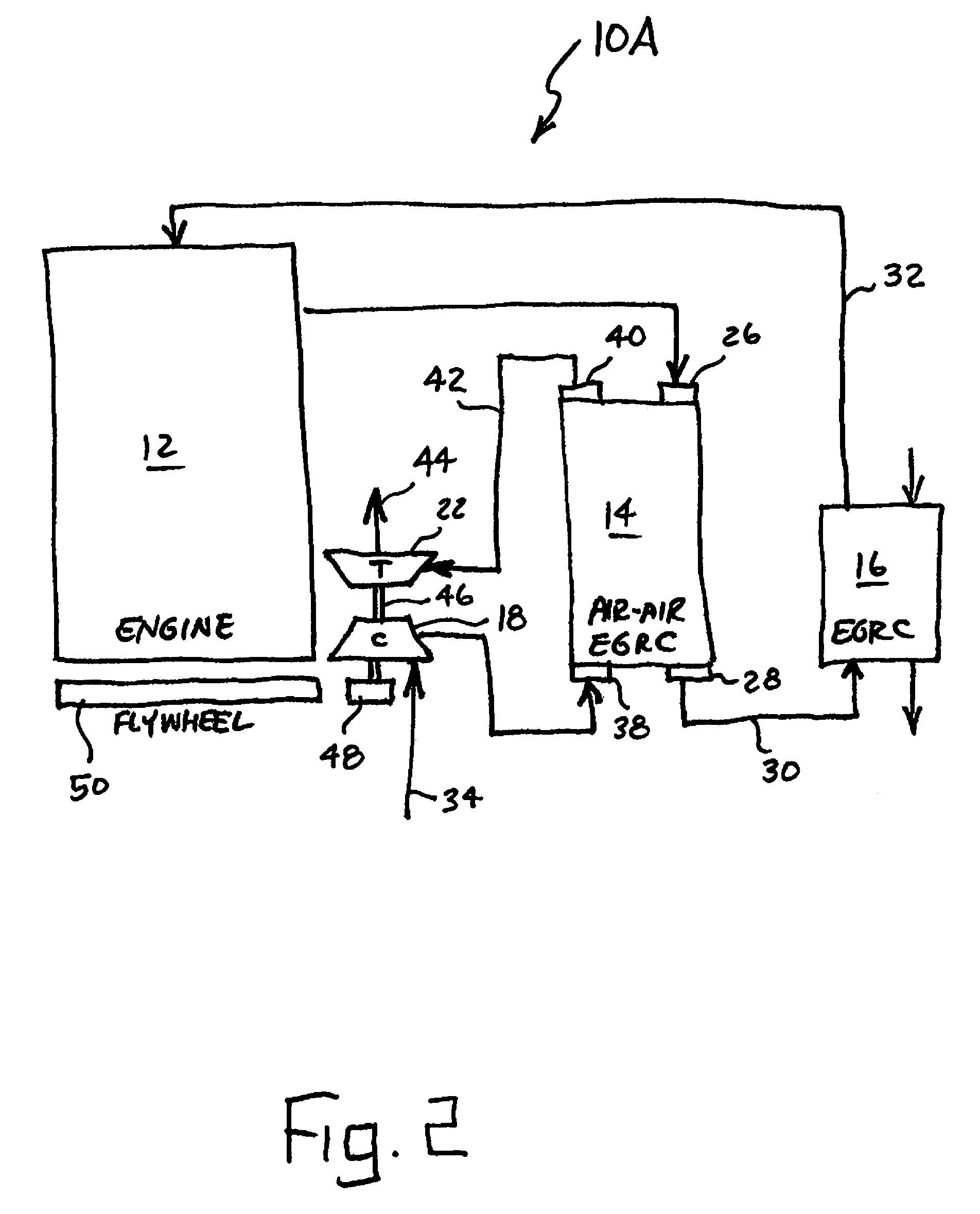
[0012]Referring now to FIG. 1, a system 10 according to one embodiment of the present invention is depicted as including an engine 12, such as a diesel engine, an air-air EGR cooler 14, a liquid EGR cooler 16, a compressor 18, a motor / generator 20, and a turbine 22. System 10 is described herein for application as a ...


PUM


Abstract

A system for reducing the temperature of waste heat from a waste heat source of a vehicle engine, including an open loop Brayton cycle having a cooler, a compressor, a turbine, and a shaft coupling the compressor to the turbine. Waste heat and compressed air from the compressor flow through the cooler, thereby transferring heat from the waste heat to the compressed air and lowering the temperature of the waste heat. The heated and compressed air is expanded across the turbine, to cause rotation of the shaft, thereby powering rotation of the compressor. Excess power beyond that necessary to drive the compressor may be drawn off through a generator which has its rotor mounted on the same shaft as the compressor and turbine.

Description

FIELD OF THE INVENTION[0001]The present invention generally relates to waste heat recovery systems for engines, and more particularly to waste heat recovery systems including an open loop Brayton cycle having a cooler, a compressor, and a turbine.BACKGROUND OF THE INVENTION[0002]In general, waste energy recovery systems for use with engines need to operate over a wide range of heat input, which varies depending upon the engine load, while maintaining acceptable performance under conditions of high fuel consumption. Various systems for adjusting system performance over a heat input range are known, such as those described in U.S. Pat. No. 6,986,251, for example.[0003]One function of engine cooling systems is to reduce the temperature of gases provided to the intake manifold of the engine in certain engine designs. Some gasoline and diesel engine systems employ exhaust gas recirculation techniques which re-route a portion of the exhaust gas from the engine, which ordinarily would be e...

Claims


Application Information

Patent Timeline
Patent Type & Authority Patents(United States)
IPC IPC(8): F02B47/08F02M25/07F02B33/44
CPCF02G5/02F02M25/0707F02M25/0731F02M25/0732F02M25/073F02G2250/03Y02T10/166Y02T10/121F02M26/05F02M26/24F02M26/27F02M26/28Y02T10/12
Inventor ERNST, TIMOTHY CNELSON, CHRISTOPHER R
Owner CUMMINS INC
Why Eureka
Try Eureka