Machining machine with means for acquiring machining parameters

a technology of machining parameters and machining machines, which is applied in the direction of grinding machine components, manufacturing tools, lapping machines, etc., can solve the problems of unsatisfactory workpiece geometry, and achieve the effects of enhancing workpiece quality, reducing damage on workpiece surfaces, and improving working operations

Inactive Publication Date: 2011-06-21
PETER WOLTERS GMBH
View PDF8 Cites 6 Cited by
  • Summary
  • Abstract
  • Description
  • Claims
  • Application Information

AI Technical Summary

Benefits of technology

[0010]The present invention is based on the objective to improve a machining machine of the aforementioned type such that it features means for acquiring at least one operation parameter, which can be arranged and read off in a simple form.
[0017]Altogether, the use of sensor elements of the invention permits an improvement of the working operations, an enhancement of the workpiece quality, a reduction of the damage on workpiece surfaces and of the necessity of repeated machining. In addition, the idle time of the machining machine can be reduced.

Problems solved by technology

However, it has been proven that thermal expansion effects influence the machining gap and lead to an undesired workpiece geometry.

Method used


Image

  • Machining machine with means for acquiring machining parameters
  • Machining machine with means for acquiring machining parameters

Examples


Embodiment Construction

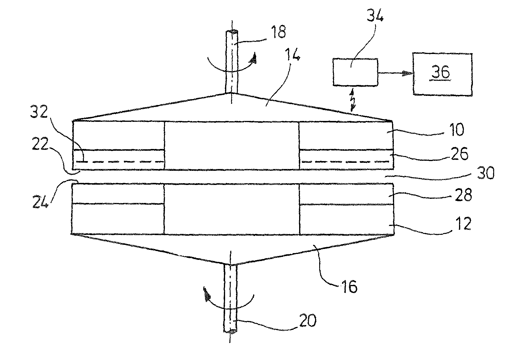
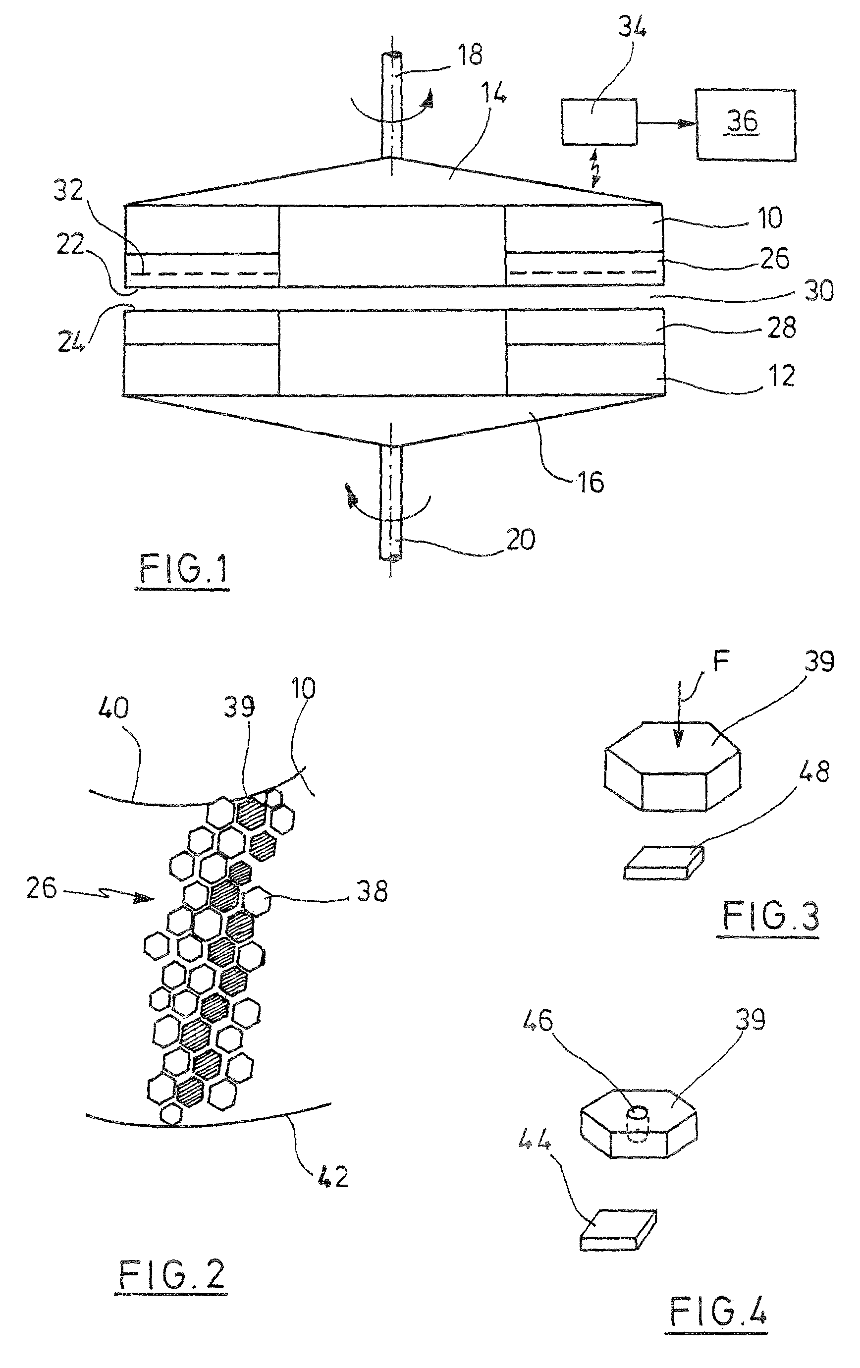
[0023]An upper machining disc 10 and a lower machining disc 12 have each at a time a carrier disc 14 or 16, respectively, which can be rotatingly driven with the aid of a vertical driving shaft 18 or 20, respectively. The driving means of the machining discs as well as their mounting and also the possibility to swivel off the upper machining disc 10 in order to get access to workpieces between the machining discs is not depicted. Such a double side machining machine is commonly known.

[0024]The machining discs 10, 12 feature machining planes 22 and 24, respectively, which face each other. They are formed by cloths, like polishing or grinding cloths for instance, or even by a coating of an abrasive material, as is depicted in the present case at 26 and 28, respectively. The machining planes 22, 24 form a machining gap 30, which has to feature a constant width across its entire extension, as far as possible, in order to ensure plane parallel machining of workpieces in the machining gap...


PUM

PropertyMeasurementUnit
radiusaaaaaaaaaa
resonant frequencyaaaaaaaaaa
thermal expansionaaaaaaaaaa

Abstract

A machining machine with an upper rotatingly drivable machining disc, the annular machining plane of which has a machining coating and is facing a lower machining plane, wherein the machining planes form a machining gap between each other. Plural rotor discs are arranged in the gap, which accommodate workpieces in recesses and which can be brought into rotation by means of a roll-off device, wherein the workpieces move along a cycloid path, wherein plural sensor elements for acquiring at least one machining parameter are arranged in the upper machining disc, distributed across its cross section, the sensor elements are each one coupled to an active or passive RFID chip and a reading device is assigned to the upper machining disc for reading out the RFID chips.

Description

CROSS REFERENCE TO RELATED APPLICATIONS[0001]This application is based upon and claims priority under 35 USC §119 to DE 10 2007 011 880.7, filed Mar. 13, 2007, entitled: MACHINING MACHINE WITH MEANS FOR ACQUIRING MACHINING PARAMETERS, the entire contents of which is herein incorporated by reference.FIELD OF THE INVENTION[0002]The present invention is related to a machining machine with means for acquiring machining parameters.BACKGROUND OF THE INVENTION[0003]The present invention is related to a machining machine having at least one upper machining disc with annular machining plane, which is rotatingly drivable around a vertical axis. A lower machining plane is assigned to the upper machining plane, which is either stationary or mounted on a lower machining disc. Between the machining planes, a machining gap is formed, in which rotor discs are arranged, which accommodate workpieces in recesses. On their part, the rotor discs are brought into a rotational movement with the aid of a r...

Claims


Application Information

Patent Timeline
Patent Type & Authority Patents(United States)
IPC IPC(8): B24B49/00B24B37/015B24B37/08
CPCB24B7/17B24B37/015B24B49/16H04Q9/00B24B37/08Y10T409/305824
Inventor FISCHER, HARALD
Owner PETER WOLTERS GMBH
Why Eureka
Try Eureka