Methods of removing aerosols from the atmosphere

a technology of aerosols and aerosols, which is applied in the direction of rhombic antennas, non-resonant long antennas, applications, etc., can solve the problems of significant electrical charge loss and inability to measure significant effects, and achieve efficient and optimal atmospheric ionization, increase the efficiency of ion emission from antennas, and increase the effect of atmospheric ionization levels

Inactive Publication Date: 2011-06-21
IONOGENIES CORP
View PDF7 Cites 2 Cited by
  • Summary
  • Abstract
  • Description
  • Claims
  • Application Information

AI Technical Summary

Benefits of technology

[0035]The present invention provides methods for increasing the ionization levels in the atmosphere to remove unwanted aerosols or particulates such as suspended pollutants. The methods utilize an ionization station having a direct current, high voltage power supply, a thin wire antenna having an inner portion in electrical communication with an outer peripheral portion for efficient and optimal atmospheric ionization, and a monitoring and control system. The configuration of the antenna yields an attenuation factor considerably less than the ones in a conventional single straight line, “L” or “T” shaped antennas, thus increasing efficiency of ion emissions from the antenna. In addition, the more compact shape of the antenna minimizes the area required for effectiveness.
[0036]The antenna of the present invention enhances the ability to broadcast ions into the atmosphere. The antenna for broadcasting or releasing ions into the atmosphere comprises a central node coupled to a number of peripheral nodes by a conductive element such as a wire or cable. At each peripheral node, the conductive element couples that peripheral node to the central node in a radial fashion. The conductive element is also coupled to adjacent peripheral nodes forming conductive peripheral spokes. The antenna further includes a support structure to support the central node and each peripheral node. All nodes of the antenna are electrically isolated from the support structure of the antenna so that the conductive element conducts electricity. The support structure of the antenna includes vertical peripheral members to support the peripheral nodes of the antenna and a vertical central member to support the central node. The shape of the antenna is similar to an inverted cone. Direct current electric power is applied to the conductive element to release a flow of ions into the atmosphere.
[0037]The present invention beneficially reduces the size of the antenna and, consequently, the amount of land required for such an antenna. The reduced size of the antenna also simplifies the installation and maintenance of the antenna in the present invention.

Problems solved by technology

Lacking modem instrumentation, he was unable to measure significant effects
While it is true that the production of GCR ions is asymmetrical, it is also true that ion recombination (neutralization of charge due to attachment of ions of opposite polarity) produces a significant loss of electrical charge.

Method used


Image

  • Methods of removing aerosols from the atmosphere
  • Methods of removing aerosols from the atmosphere
  • Methods of removing aerosols from the atmosphere

Examples


examples

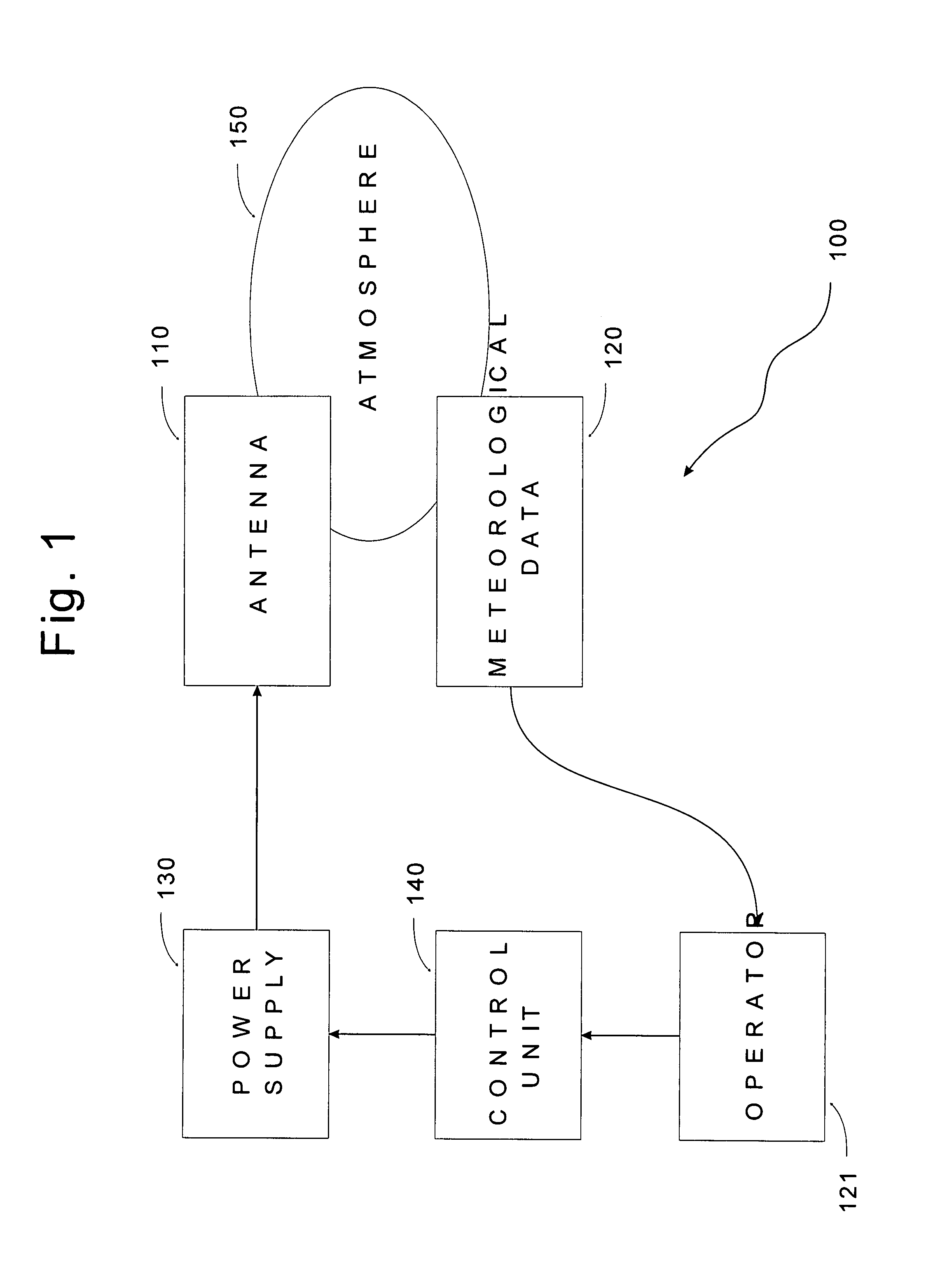
[0067]An experiment was conducted by installing and operating an ionization station. The ionization station was operated in several modes: Positive (positive voltage), Negative (negative voltage) and Non Operational (zero voltage, the station was turned off). The goal of the experiment was to determine what, if any, the effect or effects of the station would be on the surrounding atmosphere.

Equipment and Resources

Ionization Station

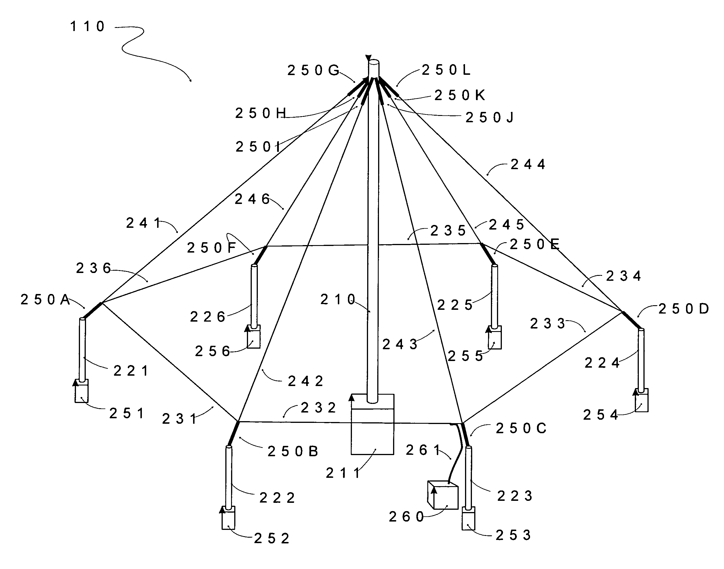
[0068]1. High Voltage, Direct Current Power Supplies. Two supplies were used. The first was made by Matsusaka Corp. of Japan, Model AU-120R10, with manually switchable polarity (positive or negative), 0 to 120,000 volts, 0 to 10 miliamperes. The other power supply was a Spellman High Voltage Electronics Corp. SL 80P150 / 230, positive polarity, 0 to 80,000 volts, 0 to 2 miliamperes.[0069]2. Antenna. The configuration included a 120′ tall guyed central tower (25 G) manufactured by Rohn Industries, Inc. designed per EIA / TIA 22-f Standards. Ten 30′ tall aluminu...


PUM


Abstract

An antenna is disclosed to efficiently ionize the atmosphere for the purpose of reducing the aerosol counts, and therefore the number of poluted particles in suspension in the atmosphere, by deposition to ground. The antenna includes peripheral nodes and a central node. Each of the peripheral nodes is connected to adjacent peripheral nodes through peripheral spokes. The peripheral nodes are also connected to the central node through radial spokes. Electric power is applied to the peripheral spokes and the radial spokes causing the antenna to charge the atmosphere through the emission of ions. The antenna minimizes an attenuation factor that reduces ionization efficiency and reduces the land requirements for its installation.

Description

REFERENCE TO RELATED APPLICATIONS[0001]This application is a continuation-in-part of U.S. patent application Ser. No. 10 / 719,565, entitled “Ionization Antenna”, the contents of which are incorporated herein by reference.FIELD OF THE INVENTION[0002]The present invention relates generally to methods of removing aerosols or particulates, such as suspension of polluted aerosols, from the atmosphere. More particularly, the invention relates to methods for electrifying the atmosphere with ion emissions by corona effect to remove unwanted aerosols or particulates by deposing these aerosols to ground.BACKGROUND OF THE INVENTION[0003]In the late 1950's Dr. Bernard Vonnegut, after having invented the silver-iodide flare in 1948 that was used for cloud seeding, and still is, almost 60 years later, pioneered ionization technology by conducting experiments that produced unipolar corona effect ions using a direct current power supply feeding high voltage to a long, thin wire electrically isolated...

Claims


Application Information

Patent Timeline
Patent Type & Authority Patents(United States)
IPC IPC(8): H01T23/00H01Q1/36A01G15/00H01Q9/34H01Q11/06F25C3/04H01Q13/00
CPCH01Q1/366H01Q9/44H01Q9/40
Inventor KAUFMAN, PHILLIP
Owner IONOGENIES CORP
Why Eureka
Try Eureka