
Erosion resistant surface and method of making erosion resistant surfaces

a technology of erosion resistance and erosion resistance, which is applied in the direction of sealing/packing, record information storage, and well accessories, etc., can solve the problems of less efficient operation of the mud motor, and the additional cost of pulling the entire drill string from the well to replace or repair the failing componen

Inactive Publication Date: 2011-06-28
SCHLUMBERGER TECH CORP
View PDF2 Cites 15 Cited by
  • Summary
  • Abstract
  • Description
  • Claims
  • Application Information

AI Technical Summary

Problems solved by technology

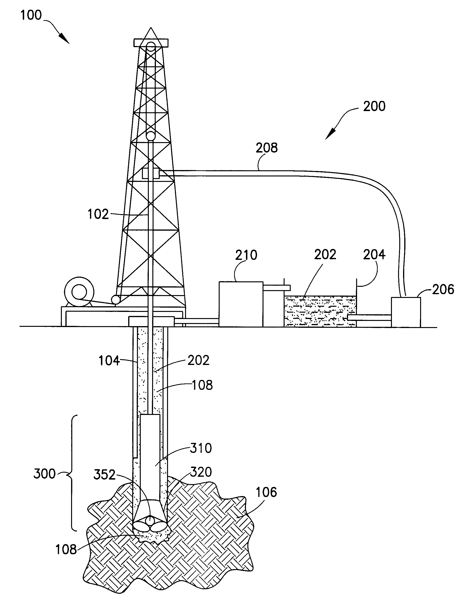
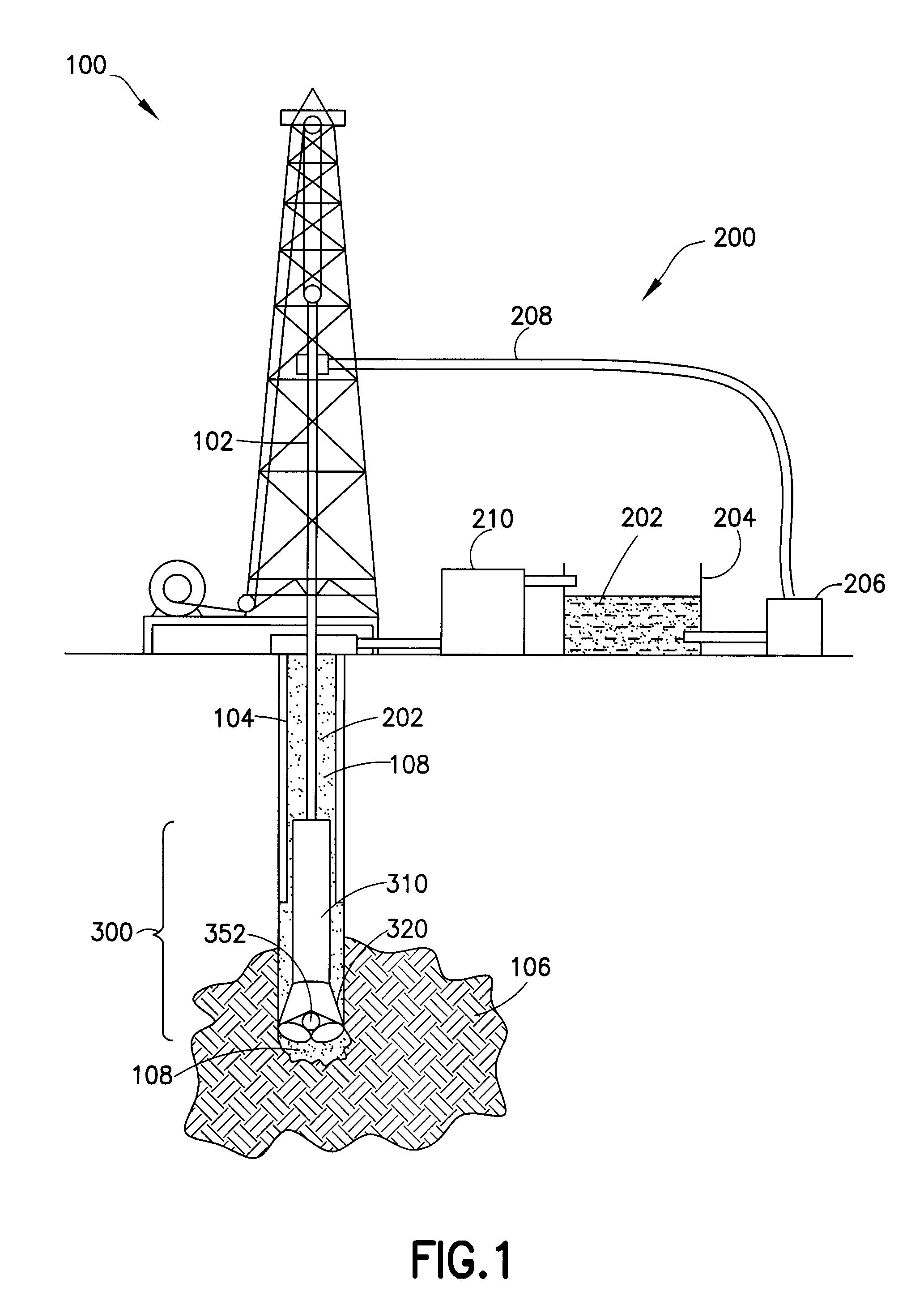
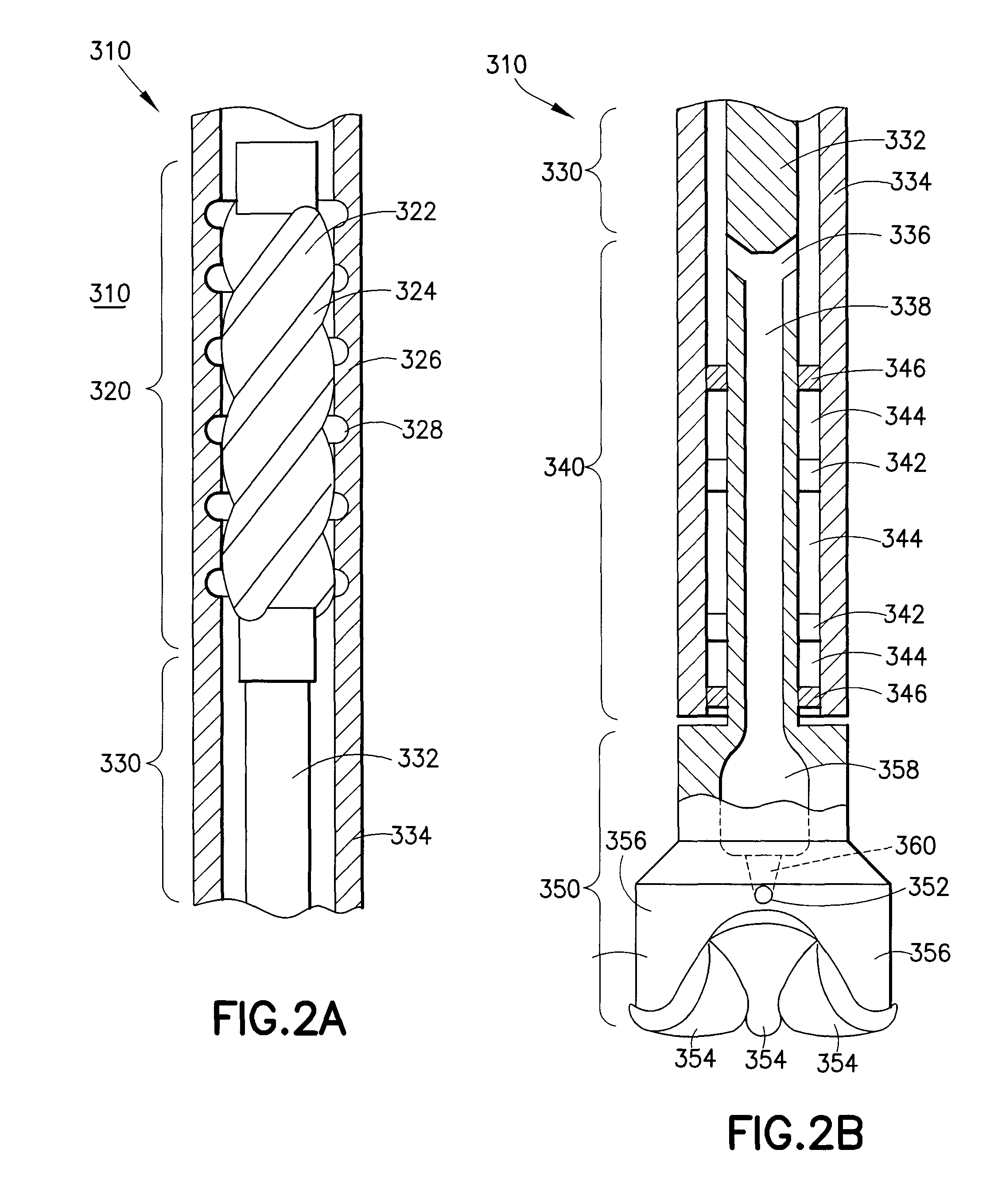
In the power section 320, the contact point between the vanes 324 and inner surface of the stator 324 is particularly susceptible to erosive wear; material loss at this juncture can permit drilling mud 202 to flow between the rotor and the stator, resulting in less efficient operation of the mud motor 310.
All of these problems include the additional cost of pulling the entire drill string from the well to replace or repair the failing component.

Method used


Image

  • Erosion resistant surface and method of making erosion resistant surfaces
  • Erosion resistant surface and method of making erosion resistant surfaces
  • Erosion resistant surface and method of making erosion resistant surfaces

Examples


example

[0034]Assume that an incoming erosive particle buckles a carbon nanotube in a perfectly elastic manner. The buckling stress for a cylinder F, is:

[0035]f=π2⁢EI4⁢L2

where E is the elastic modulus of the carbon nanotube, L is the length and I is the moment of inertia. A carbon nanotube is a hollow cylinder so I is given as:

[0036]I=π⁡(r24-r14)4

where r1 is the inner radius and r2 is the outer radius. Assume that the force prior to buckling is negligible and that the post-buckling force is constant. If a carbon nanotube is deflected to half its height by an impacting particle, then the energy absorbed by the nanotube, W, will be:

[0037]W=π3⁢E⁡(r24-r14)32⁢L

[0038]Assume that the individual carbon nanotubes within the forest are arranged in a square matrix on the substrate and separated by a distance of 2r2. Further, assume that a cubic sand particle, with length d on each edge, and density ρ, is traveling with velocity ν, and impacts normal to the surface. Then the number of carbon nanotubes ...


PUM

PropertyMeasurementUnit
lengthaaaaaaaaaa
lengthaaaaaaaaaa
lengthaaaaaaaaaa

Abstract

An erosion resistant surface using a dense array of elastic whiskers to slow the velocity of erosive particles before impacting with the surface. A carbon nanotube forest is grown on the surface to provide the erosion resistance. In the alternative, a carbon nanotube forest is grown on a flexible substrate that is bonded to the surface.

Description

TECHNICAL FIELD[0001]The present invention relates to controlling erosion on apparatuses exposed to highly erosive environments. More particularly, the present invention relates to application of a dense network of elastic fibers to wellbore tools and equipment.BACKGROUND OF THE INVENTION[0002]Erosive wear occurs when a surface is exposed to a flow of material in a fluid. Particles within the fluid impact on the exposed surface and impart some of their kinetic energy into the exposed surface. If sufficiently high, the kinetic energy of the impacting particles creates significant tensile residual stress in the exposed surface, below the area of impact. Repeated impacts cause the accumulation of tensile stress in the bulk material that can leave the exposed surface brittle and lead to cracking, crack linkage and gross material loss.[0003]Erosive wear is a cause for concern in applications as diverse as hydroelectric turbines, jet engine turbine blades, aircraft surfaces and wellbore d...

Claims


Application Information

Patent Timeline
Patent Type & Authority Patents(United States)
IPC IPC(8): E21B7/12E21B34/04E21B10/00
CPCE21B4/02E21B10/46Y10T428/292Y10T428/26Y10S977/742
Inventor HUMPHREYS, ALANDOWNTON, GEOFF
Owner SCHLUMBERGER TECH CORP
Learn More