
Reduction of air damping in MEMS device

a technology of air damping and mems, which is applied in the direction of relays, generators/motors, contacts, etc., can solve the problems that the venting hole does not allow fluid/gas to enter the area, and achieve the effect of reducing air damping, reducing the space for movement, and increasing the opening and closing speed of the devi

Inactive Publication Date: 2011-06-28
QUALCOMM TECHNOLOGIES INC
View PDF20 Cites 3 Cited by
  • Summary
  • Abstract
  • Description
  • Claims
  • Application Information

AI Technical Summary

Benefits of technology

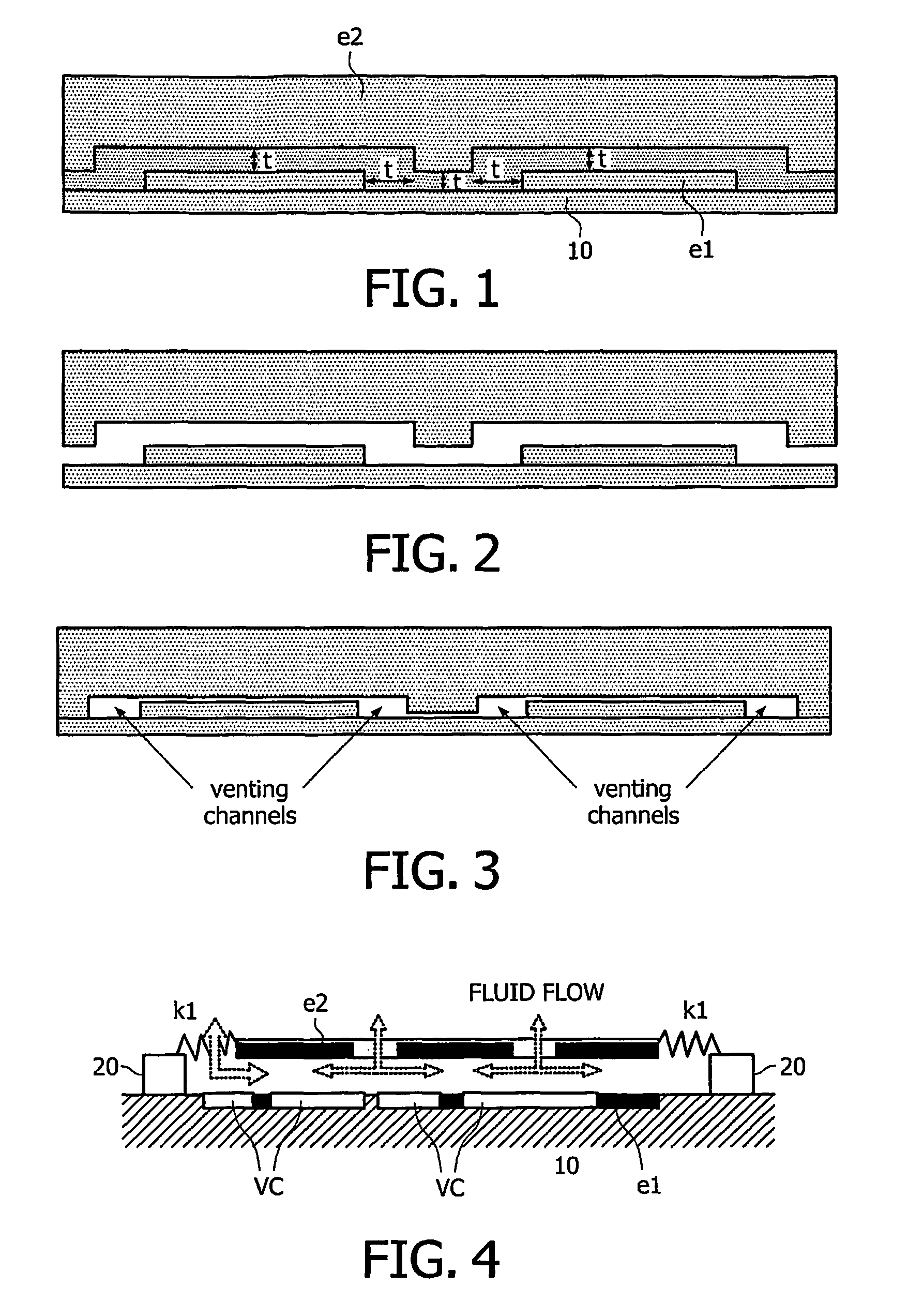
[0016]The fact that the channels allow fluid to enter the area between the facing surfaces is an important advantage of the present invention.

Problems solved by technology

Venting holes do not allow fluid / gas to enter the area between the facing surfaces because the surfaces are not facing each other at the position of the venting hole.

Method used


Image

  • Reduction of air damping in MEMS device
  • Reduction of air damping in MEMS device
  • Reduction of air damping in MEMS device

Examples


Embodiment Construction

[0033]The present invention will be described with respect to particular embodiments and with reference to certain drawings but the invention is not limited thereto but only by the claims. The drawings described are only schematic and are non-limiting. In the drawings, the size of some of the elements may be exaggerated and not drawn on scale for illustrative purposes. Where an indefinite or definite article is used when referring to a singular noun e.g. “a” or “an”, “the”, this includes a plural of that noun unless something else is specifically stated.

[0034]Furthermore, the terms first, second, third and the like in the description and in the claims, are used for distinguishing between similar elements and not necessarily for describing a sequential or chronological order. It is to be understood that the terms so used are interchangeable under appropriate circumstances and that the embodiments of the invention described herein are capable of operation in other sequences than descr...


PUM


Abstract

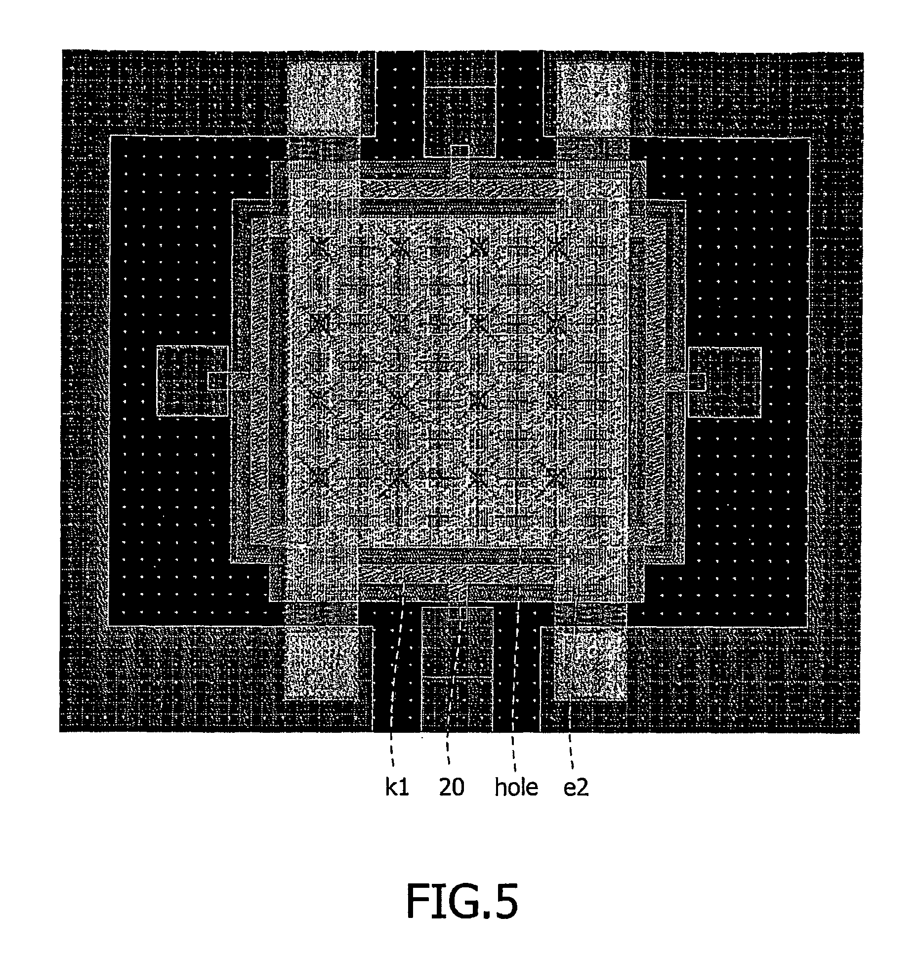
A micro-electromechanical device has a substrate (10), a movable element, movable towards the substrate by electrostatic forces on electrodes, facing surfaces of the movable element and the substrate being shaped such that one or more venting channels (VC) are defined by the facing surfaces when they are in a closed position, configured to enable fluid between the facing surfaces to flow across the facing surfaces, to enter or exit the area between the facing surfaces. Such channels can enable fluid damping of the movement of the moveable element to be controlled. Increasing the flow entering or exiting the area between the facing surfaces, can reduce such damping, and hence increase speed of opening and closing of the device. The channels can connect to holes in the electrodes.

Description

TECHNICAL FIELD[0001]This invention relates to MEMS devices, to semiconductor devices such as integrated circuits and to apparatus incorporating such MEMS devices, and to methods of offering communication services over such devices.BACKGROUND[0002]The term ‘MEMS’ (Micro-electromechanical system or structure or switch) can encompass various devices. A common arrangement of a MEM device comprises a freestanding beam with a first electrode located opposite a second electrode. The first and the second electrode are mutually separated by an air gap. The first electrode can be moved towards or away from the second electrode by application of an actuation voltage to provide an electrostatic force (in principle other forces could be used such as an inductive force).[0003]Some common applications are:[0004]use as a microphone or a loudspeaker; (using a specific type of membrane)[0005]use as a sensor, particularly an air pressure sensor[0006]use as a resonator[0007]use as pixel switches in a ...

Claims


Application Information

Patent Timeline
IPC IPC(8): H01H51/22
CPCB81B3/0059H01G5/16H01H59/0009B81B2201/0257H01H2001/0084B81B2201/0264
Inventor STEENEKEN, PETER G.VAN BEEK, JOZEF THOMAS MARTINUSRIJKS, THEODOOR
Owner QUALCOMM TECHNOLOGIES INC
Learn More