System and method for calibration verification of an optical particle counter

a technology of optical particle counter and calibration verification method, which is applied in the field can solve the problems of high power consumption, large particle generator pump 102/b>, and difficult calibration process of optical particle counter, and achieve the effect of fast determining the calibration status and low power consumption

Active Publication Date: 2011-07-05
PARTICLE MEASURING SYST
View PDF30 Cites 33 Cited by
  • Summary
  • Abstract
  • Description
  • Claims
  • Application Information

AI Technical Summary

Benefits of technology

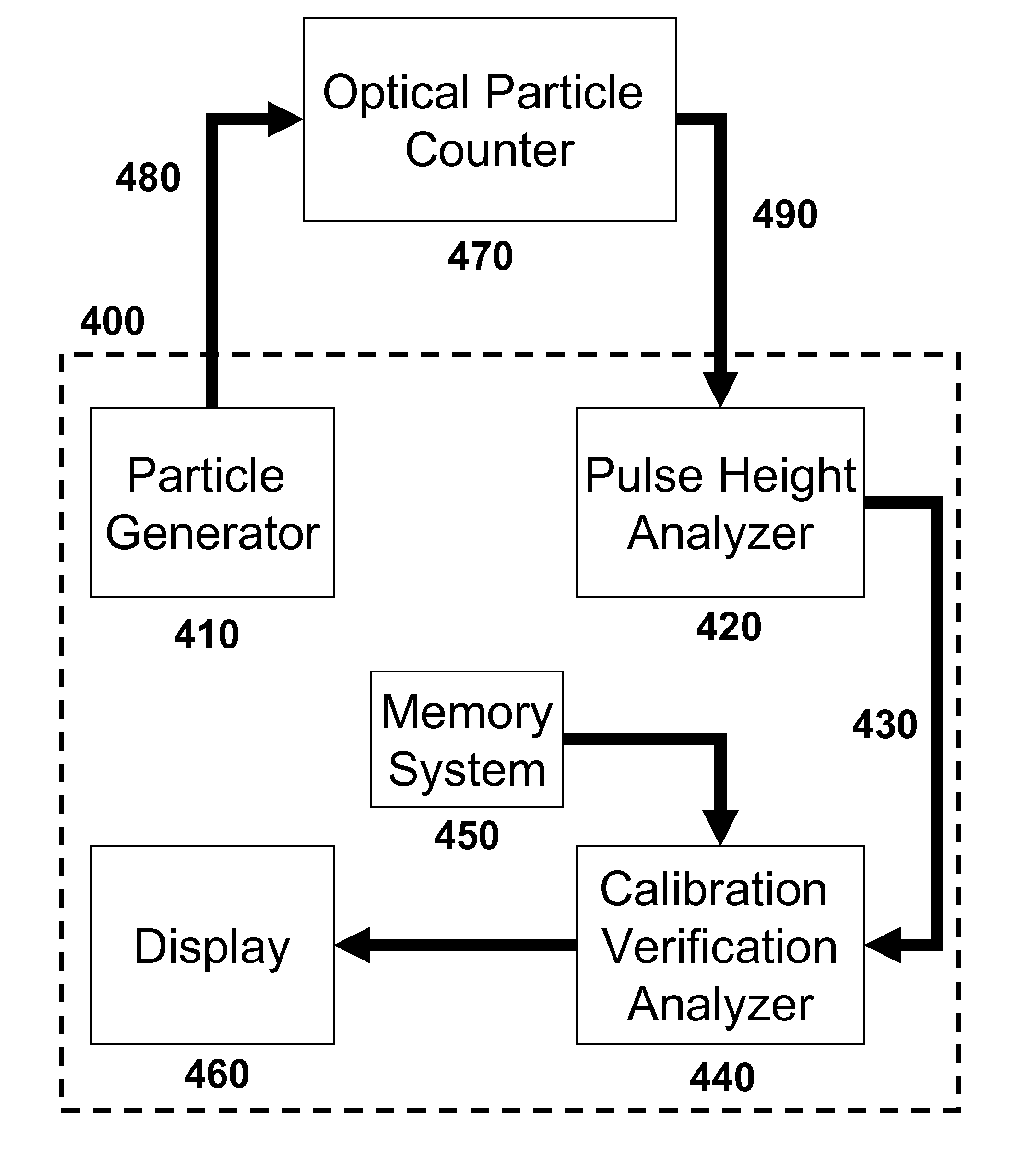
[0019]Described herein is a portable, low power consuming optical particle counter calibration verification system and reliable and sensitive methods for verifying the calibration status of a gas or liquid particle counter. The calibration verification systems described herein are useful for quickly determining the calibration status of an optical particle counter at its point of use, as well as for allowing the end user to determine if an optical particle counter is in need of a recalibration before the recommended calibration schedule suggests.
[0027]In an embodiment, the particle counter undergoing calibration verification is tested under conditions where no particles are present in the particle counter. Such conditions are useful for the determination of the particle counter's false count rate. In an embodiment, a series of false count rates are determined for a variety of threshold voltages / pulse heights and fit to a line or curve. Here, the slope of the best fit line (i.e., slope of the noise floor) is useful, for example, in that it allows for extrapolation to larger threshold values where the false count frequency is smaller and an accurate determination of the actual false count rate could take a long time. In an embodiment, the false count rate is prespecified to be a false count rate larger than an acceptable count rate and the extrapolation allows for determination of such a zero count failure point; that is, the threshold voltage at which the prespecified false count rate is expected to fall. In an embodiment, the zero count failure point is equivalent to the particle counter's noise level, and a useful signal to noise ratio can be determined from the ratio of the median of the pulse height distribution for particles having a preselected size distribution to the zero count failure point of the particle counter.

Problems solved by technology

The calibration process for an optical particle counter is complicated and usually requires trained representatives from the particle counter manufacturer to perform the calibration.
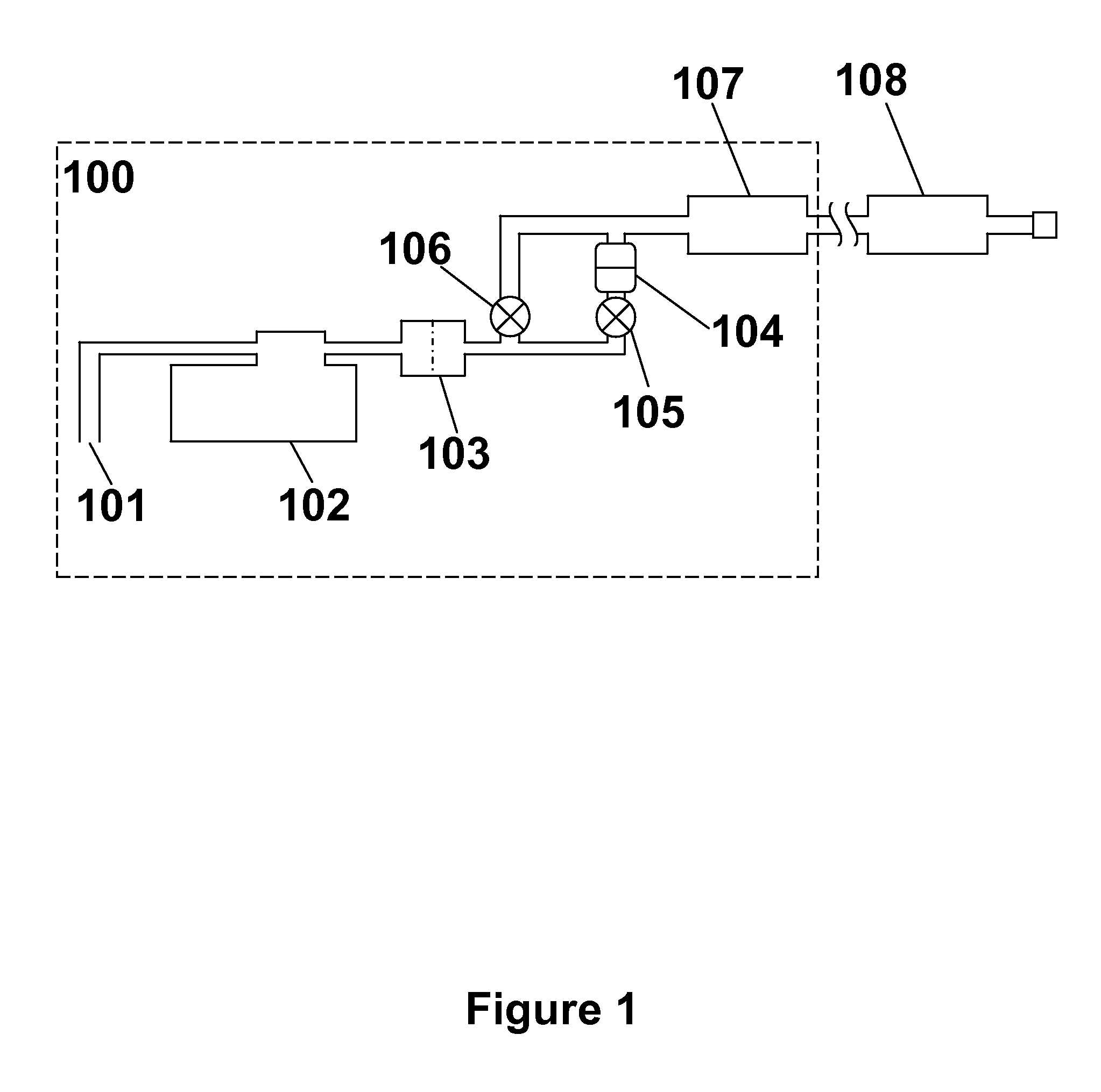
The particle generator pump 102 is typically large, heavy, and power consuming, generally requiring AC power.
This test is very time consuming and may require an extended total sampling time of over an hour.
A full optical particle counter calibration is complicated and, thus, generally must be performed by a trained representative from the particle counter manufacturer.
A full calibration typically requires a large amount of test equipment which is not portable.
If an aerosol optical particle counter drifts out of calibration in one of these clean areas, the particle counter may over- or under-count the particle level in the clean area.
If the particle counter is under-counting, the clean area may be dirtier than the user believes.
In a worst case scenario, the user may experience a drop off in wafer yield due to this undetected particle contamination.
An out of calibration particle counter also presents significant problems to a pharmaceutical user.
If a particle counter is under-counting, the clean process area may be dirtier than the user believes.
For example, if a liquid source includes particle levels higher than expected, this may result in an end product, of which this liquid which is a component, having contamination levels higher than expected.
As above, this may pose a significant problem, for example if the end product is a pharmaceutical composition.
Alternatively, if the liquid is utilized, for example, as a rinse, wash or solvent during the processing of a semiconductor device, particle contamination of the semiconductor device may result, resulting in decreased semiconductor device yield.
If it is determined that the particle counter sufficiently under-counted so as to place the actual clean area it monitored above the allowed FDA specified contamination limit, all product produced in that area for the entire year becomes suspect.
This is a disaster that could cost the pharmaceutical user millions of dollars in lost product.
The primary drawback to these and similar methods and systems is that they do not employ actual particles for testing the optical particle counter.
Although this method is useful and uses standardized particles, it appears to only consider counting accuracy and is practical only for particle counters which measure particles suspended in a liquid.
Optical particle counters may become mis-calibrated for a number of reasons including drift in the detection electronics; such a mis-calibrated particle counter may still properly count the total number of particles but may misidentify the real sizes of particles.

Method used


Image

  • System and method for calibration verification of an optical particle counter
  • System and method for calibration verification of an optical particle counter
  • System and method for calibration verification of an optical particle counter

Examples


example 1

Portable Particle Counter Calibration Verification System

[0078]FIG. 6 details the major design features of an aerosol optical particle counter which detects particles based on scattered electromagnetic radiation. A laser source 601 including a laser diode 602 is generally employed to generate a laser beam 603 that is then shaped and focused by beam shaping optics 604 into an optical sample chamber 605. Ambient air is drawn into the sample chamber through an inlet jet 606 by the instrument's flow system. The inlet jet 606 shapes the sample air flow in order to ensure all of the air flow is passed through the laser beam 603.

[0079]When a particle is carried into the sample chamber 605 by the sample air flow, it scatters light energy as it passes through the laser beam 603. The scattered light energy is collected by the sample chamber's collecting optics (4 mangin mirrors 607 and retro-reflector mirror 608 in the example shown in FIG. 6) and focused onto a photodiode 609.

[0080]The photo...


PUM

PropertyMeasurementUnit
sizeaaaaaaaaaa
sizeaaaaaaaaaa
sizeaaaaaaaaaa

Abstract

Described herein is a portable, low power consuming optical particle counter calibration verification system and reliable and sensitive methods for verifying the calibration status of a gas or liquid particle counter. The calibration verification systems described herein are useful for quickly determining the calibration status of an optical particle counter at its point of use, as well as for allowing the end user to determine if an optical particle counter is in need of a recalibration before the recommended calibration schedule suggests.

Description

CROSS REFERENCE TO RELATED APPLICATION[0001]This application claims priority under 35 U.S.C. §119(e) to U.S. Provisional Patent Application No. 60 / 988,515 filed on Nov. 16, 2007, which is hereby incorporated by reference in its entirety.STATEMENT REGARDING FEDERALLY SPONSORED RESEARCH OR DEVELOPMENT[0002]Not Applicable.BACKGROUND OF THE INVENTION[0003]This invention is in the field of optical particle counters. This invention relates generally to calibration verification systems and methods for verifying the calibration status and performance of optical particle counters.[0004]A large portion of the micro-contamination industry is reliant on the use of optical particle counters, such as are described in a large number of U.S. patents, including U.S. Pat. Nos. 3,851,169, 4,348,111, 4,957,363, 5,085,500, 5,121,988, 5,467,188, 5,642,193, 5,864,399, 5,920,388, 5,946,092, and 7,053,783. U.S. Pat. Nos. 4,728,190, 6,859,277, and 7,030,980, also disclose optical particle counters and are he...

Claims


Application Information

Patent Timeline
Patent Type & Authority Patents(United States)
IPC IPC(8): G01N15/02
CPCG01N15/1012G01N2015/1018
Inventor BATES, THOMAS
Owner PARTICLE MEASURING SYST
Why Eureka
Try Eureka