
Loudspeaker system

a loudspeaker and speaker technology, applied in the direction of substation equipment, electrical transducers, electrical apparatus casings/cabinets/drawers, etc., can solve the problems of difficult to realize a loudspeaker system compact and capable of reproducing low-pitched sound, and achieve low-pitched sound reproduction, stable performance, and the effect of deterioration of the absorbent sealed into the package body

Active Publication Date: 2011-07-05
PANASONIC CORP
View PDF20 Cites 36 Cited by
  • Summary
  • Abstract
  • Description
  • Claims
  • Application Information

AI Technical Summary

Benefits of technology

"The present invention relates to a loudspeaker system that expands the low-pitched sound reproduction band by utilizing a physical absorption phenomenon induced by an absorbent. The system includes a cabinet, a speaker unit, a package body, a filler gas, and an absorbent. The absorbent is a porous material such as activated carbon, zeolite, silica, alumina, zirconia, magnesia, ferrosoferric oxide, molecular sieve, fullerene, or carbon nanotube. The package body is structured by a bag body or has an accordion structure. The system prevents a decrease in function of physical absorption of the absorbent and maintains good low-pitched sound characteristics."

Problems solved by technology

Conventionally, due to acoustic stiffness which a vacant space of a speaker cabinet causes, it has been difficult to realize a loudspeaker system which is compact and capable of reproducing low-pitched sound.

Method used


Image

  • Loudspeaker system
  • Loudspeaker system
  • Loudspeaker system

Examples


first embodiment

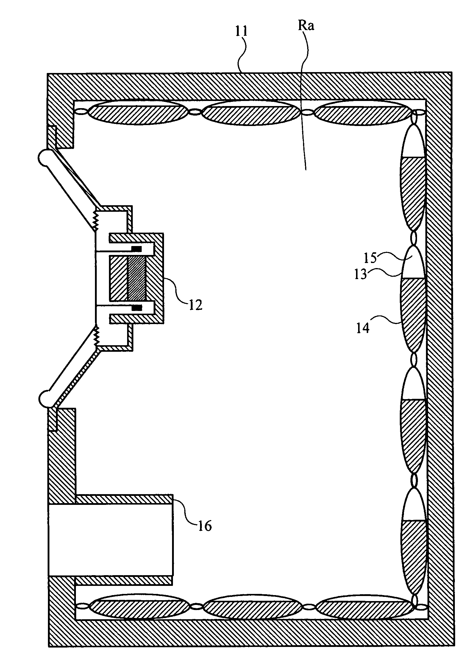
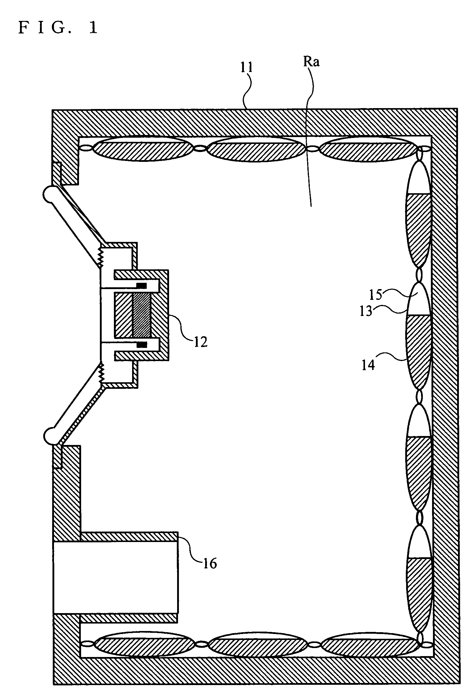
[0066]Referring to FIG. 1, a loudspeaker system according to a first embodiment of the present invention will be described. In the loudspeaker system described below, as one example of a phase inversion-type speaker cabinet, a bass reflex-type speaker cabinet is employed. FIG. 1 is a schematic diagram illustrating a cross-sectional view of an internal structure of the loudspeaker system.

[0067]In FIG. 1, the loudspeaker system comprises a cabinet 11, a speaker unit 12, a package body 13, an absorbent 14, a filler gas 15, and an acoustic port 16.

[0068]The cabinet 11 has a front face, a back face, an upper face, a lower face, and right and left side faces of a housing of the loudspeaker system. The speaker unit 12 is an electrodynamic speaker and mounted at an opening of the front face of the cabinet 11. And a vacant space Ra of the loudspeaker system is formed inside of the cabinet 11.

[0069]The acoustic port 16 is provided on the front face of the cabinet 11 and the vacant space Ra fo...

second embodiment

[0087]Referring to FIG. 3, a loudspeaker system according to a second embodiment of the present invention will be described. In the loudspeaker system, a bass reflex method similar to that of the first embodiment is employed and package bodies 13 are disposed inside of a cabinet afterward. FIG. 3 is a schematic diagram illustrating a cross-sectional view of an internal structure of the loudspeaker system.

[0088]In FIG. 3, the loudspeaker system comprises a cabinet 21, a speaker unit 22, and an acoustic port 26, having a vacant space Rb formed inside of the cabinet 21. Since these components are same as the cabinet 11, the speaker unit 12, and the acoustic port 16 described in the first embodiment, detailed descriptions on the components will be omitted.

[0089]Here, the loudspeaker system shown in FIG. 3 is a general bass reflex-type loudspeaker system. The package bodies 13 having absorbent 14 and filler gas 15 sealed thereinto are additionally disposed inside of the vacant space Rb o...


PUM


Abstract

A loudspeaker system comprises a cabinet, a speaker unit, a package body, a filler gas, and an absorbent. The speaker unit is mounted in the cabinet. At least one package body is disposed in a vacant space inside of the cabinet and is structured by a bag body for sealing materials thereinto from outside thereof. A predetermined amount of the filler gas is sealed into the package body. A predetermined amount of the absorbent is sealed into the package body and physically absorbs the filler gas.

Description

TECHNICAL FIELD[0001]The present invention relates to a loudspeaker system and more particularly, to a loudspeaker system which expands a low-pitched sound reproduction band by utilizing a physical absorption phenomenon induced by an absorbent.BACKGROUND ART[0002]Conventionally, due to acoustic stiffness which a vacant space of a speaker cabinet causes, it has been difficult to realize a loudspeaker system which is compact and capable of reproducing low-pitched sound. As a solution to a problem of the limitation in the low-pitched sound reproduction capability which depends on a cabinet volume, there has been a loudspeaker system in which a block of activated carbon is disposed inside of a cabinet (for example, refer to patent document 1). FIG. 15 is a tectonic profile of a major portion of the loudspeaker system described in the above-mentioned patent document 1.[0003]FIG. 15 is the tectonic profile of the major portion of the loudspeaker system described in the above-mentioned pat...

Claims


Application Information

Patent Timeline
Patent Type & Authority Patents(United States)
IPC IPC(8): H04R25/00H04R1/02H04R9/06H05K5/00
CPCH04R1/2803H04M1/035H04R1/2819H04R2499/11H04R2499/13
Inventor MATSUMURA, TOSHIYUKISAIKI, SHUJIKANO, SAWAKOKUZE, MITSUKAZU
Owner PANASONIC CORP
Learn More