Methods and apparatus for a cascade converter using series resonant cells with zero voltage switching

a series resonant cell and cascade converter technology, applied in the direction of electric variable regulation, process and machine control, instruments, etc., can solve the problems of complex control required for capacitor balancing, voltage imbalance between series-connected dc bus capacitors, and inability to achieve the effect of balancing the capacitors,

Active Publication Date: 2011-07-26
RAYTHEON CO
View PDF33 Cites 43 Cited by
  • Summary
  • Abstract
  • Description
  • Claims
  • Application Information

AI Technical Summary

Benefits of technology

[0015]In one aspect, at least some embodiments of the invention use a dual series resonant converter (SRC) that operates with zero voltage switching (ZVS) under all load conditions, to help eliminate some or all of the faults that may arise by spurious gate turn-on (e.g., the cross-conduction shown in the prior art FIG. 2).
[0031]In still further embodiments of this aspect, at least a portion of the dual power converter cells includes a dual SRC cell comprising first and second SRC cells and a cell controller. The first SRC cell comprises an input, a DC output, and a first AC / DC converter connected in parallel with the output of the first SRC cell, the first AC / DC converter having an output. The second SRC is operably coupled in series with the first SRC cell, and the second SRC cell comprises an input, a DC output, and a second respective power exchange circuit that includes a second respective AC / DC converter connected in parallel with the output of the second SRC cell. The second AC / DC converter has a DC output, wherein the output of the first AC / DC converter is operably coupled so as to be parallel with the DC output of the second SRC cell, and the output of the second AC / DC converter is operably coupled so as to be in parallel with the DC output of the first SRC cell. The SRC cell controller is in operable communication with the first and second SRC cells, and the SRC cell controller is configured to: sense at least one variable signal from each respective SRC cell, wherein the variable signal comprises at least one signal selected from the group consisting of input voltage, input current, output voltage, and output current; and activate, based on the value of the sensed variable signal, at least one of the first and second AC / DC converters coupled to the output of a respective SRC cell, wherein the activated AC / DC converter operates so as to change the input voltage value of the respective SRC cell to which its output is connected. The changing of the input voltage value restores an input voltage balance between the first and second SRC cells.

Problems solved by technology

One problem associated with diode-clamped converters is voltage imbalance between series-connected DC bus capacitors and complicated control required for capacitors balancing.
Another negative aspect of these converters is the unequal conduction time of switches.
As the number of levels increases (e.g., beyond five levels), the diode-clamped converter topology can become unwieldy and difficult to realize.
Another disadvantage is that the flying capacitor converters require a significant number of large capacitors with voltage rating that increases with the number of levels.
As with the diode-clamped converters, capacitor clamped inverters can be awkward and difficult to achieve beyond five levels.
However, since these converters require multiple, isolated DC sources (for example, via a separate line frequency transformer rated for full load power), their use is somewhat limited.
Although this topology has a three-phase power source, it relies on single-phase power processing that leads to oversized DC filter capacitors inside cells.
Also, because cell converters comprising this topology are connected in series on both sides of the isolation boundary, this approach does not guarantee equal power distribution between cells.
In general, known converters do not adequately address operation of fast semiconductors in high voltage (HV) switching environments that may generate a spurious turn-on.
These transients might cause simultaneous conduction of transistors connected across the input bus (cross-conduction) resulting in failures of HV, HF converters, as shown in the prior art configuration of FIG. 1.
Active pull-down gate drive circuits and reduced internal gate resistance can alleviate this problem, but they do not address its root cause.
However, parallel connection of the power cells is a limiting factor in high voltage applications.

Method used


Image

  • Methods and apparatus for a cascade converter using series resonant cells with zero voltage switching
  • Methods and apparatus for a cascade converter using series resonant cells with zero voltage switching
  • Methods and apparatus for a cascade converter using series resonant cells with zero voltage switching

Examples


Embodiment Construction

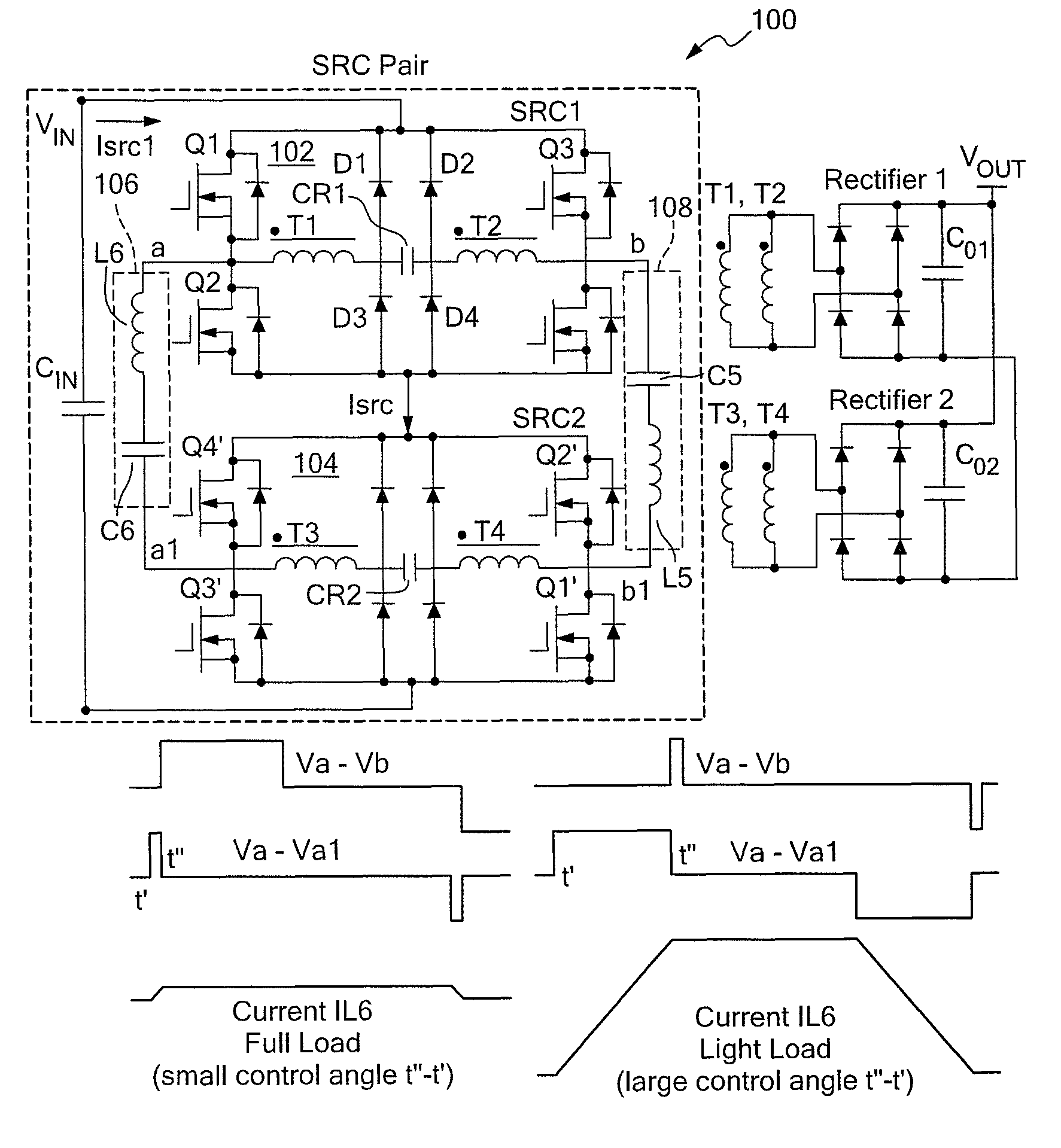
[0048]In one aspect, the invention provides a high power DC / DC conversion topology operating from a single high voltage (HV) source using a building block comprising a dual series resonant converter (SRC) with clamped capacitor voltage. Exemplary embodiments include a power topology using multiple power stages with Zero-Voltage Switching (ZVS) operation at any practical load. This topology also ensures equal input voltage and power sharing between individual converters. The inventive power cell provides enhanced reliability and efficiency compared with conventional circuits. In one embodiment, the invention builds on and improves the ZVS topology described in the commonly assigned, related, and incorporated-by-reference U.S. Pat. Nos. 6,873,138 6,873,139.

[0049]FIG. 3A shows an exemplary dual SRC power cell 100 in accordance with exemplary embodiments of the invention. The power cell 100 has ZVS under all, or substantially all, expected load and line conditions thereby reducing switc...


PUM


Abstract

A method of providing power to a load is provided. A first series resonant converter is provided. A second SRC is operably coupled to the first SRC in a cascade connected arrangement. First and second zero voltage switching (ZVS)-assistance networks are operably coupled between the first SRC and the second SRC, such that the first and second ZVS-assistance networks are providing first and second ZVS-assistant currents flowing from each ZVS-assistance network to the cascade connected arrangement of SRCs. Power from a power source is received at the cascade connected arrangement of first and second SRCs, power from a power source. The cascade connected arrangement of first and second SRCs supplies an output voltage to the load in response to receiving power from the power source.

Description

CROSS REFERENCE TO RELATED APPLICATIONS[0001]The present invention claims the benefit of U.S. Provisional Patent Application No. 60 / 950,130 filed on Jul. 17, 2007 and also claims the benefit of U.S. Provisional Patent Application No. 60 / 950,383, filed on Jul. 18, 2007, each of which is incorporated herein by reference. In addition, this application is related to U.S. Nonprovisional patent application Ser. No. 11 / 936,896, filed Nov. 8, 2007, the contents of which are hereby incorporated by reference. The present invention also is related to commonly assigned U.S. Pat. No. 6,873,138, issued Mar. 29, 2005, the contents of which are hereby incorporated by reference.STATEMENT REGARDING FEDERALLY SPONSORED RESEARCH[0002]The Government may have certain rights in the invention pursuant to contract number N00014-05-C-0202.BACKGROUND[0003]The invention relates generally to multilevel power conversion devices and more particularly to series resonant converters (SRCs) with clamped capacitor vol...

Claims


Application Information

Patent Timeline
Patent Type & Authority Patents(United States)
IPC IPC(8): H02M3/335
CPCH02M1/34H02M3/285H02M2001/0074H02M2001/0058H02M2001/342Y02B70/1491H02M2001/008H02M1/0058H02M1/0074H02M1/008H02M1/342Y02B70/10
Inventor JACOBSON, BORIS S.HOLMANSKY, EVGENY N.
Owner RAYTHEON CO
Why Eureka
Try Eureka