
Embedded logic analyzer functionality for system level environments

a logic analyzer and logic analysis technology, applied in the field of embedded logic analyzers and system level design environments, can solve the problems of reducing the usefulness of this software, not providing bit and cycle accurate simulations of hardware blocks, and wasting months in software simulating one hour of real-time operation

Active Publication Date: 2011-08-02
ALTERA CORP
View PDF49 Cites 18 Cited by
  • Summary
  • Abstract
  • Description
  • Claims
  • Application Information

AI Technical Summary

Benefits of technology

These and other features and advantages of the invention will be pres

Problems solved by technology

These simulators typically employ a floating-point numeric representation; they do not provide bit and cycle accurate simulations of the hardware blocks.
While the hardware simulation and verification software available with modern system level simulators and conventional EDA tools can often provide results that accurately predict performance of hardware designs, the increasing complexity of such designs reduces the usefulness of this software.
For example, for a typical echo canceller design, simulating one hour of real-time operation can take months in software.
Also, it is becoming increasingly difficult to obtain real-world stimulus to accurately model a full system design such as that provided as a system on a programmable chip (SOPC).
Still further, algorithm designers face the difficulty of having to use more than one tool for various stages of the design cycle (e.g., a system level simulator for high level designs and a conventional EDA simulator for simulations of more specific hardware designs).
And in addition to the difficulties in generating a comprehensive simulation, other circuit board variables such as temperature changes, capacitance, noise, and other factors may cause intermittent failures in a device that are only evident when the hardware is operating within a working system.

Method used


Image

  • Embedded logic analyzer functionality for system level environments
  • Embedded logic analyzer functionality for system level environments
  • Embedded logic analyzer functionality for system level environments

Examples


example)

HDL Code (Example)

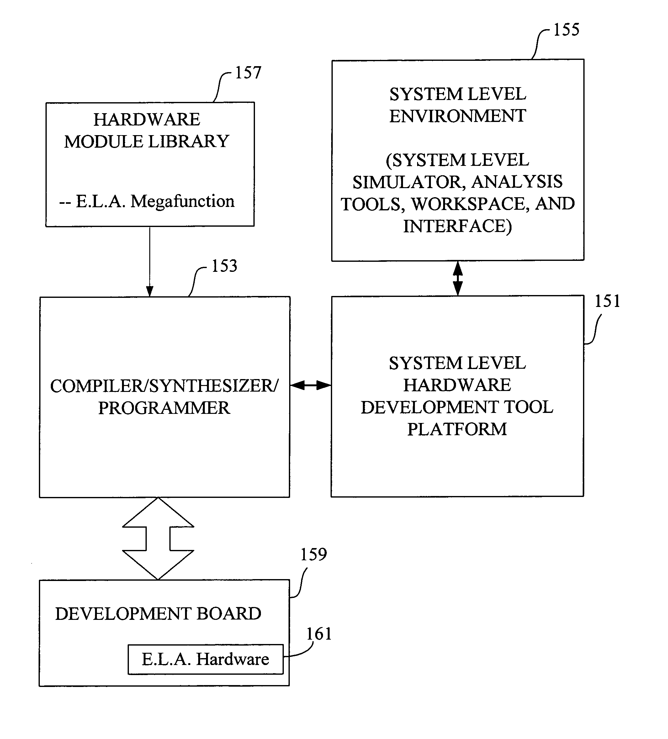
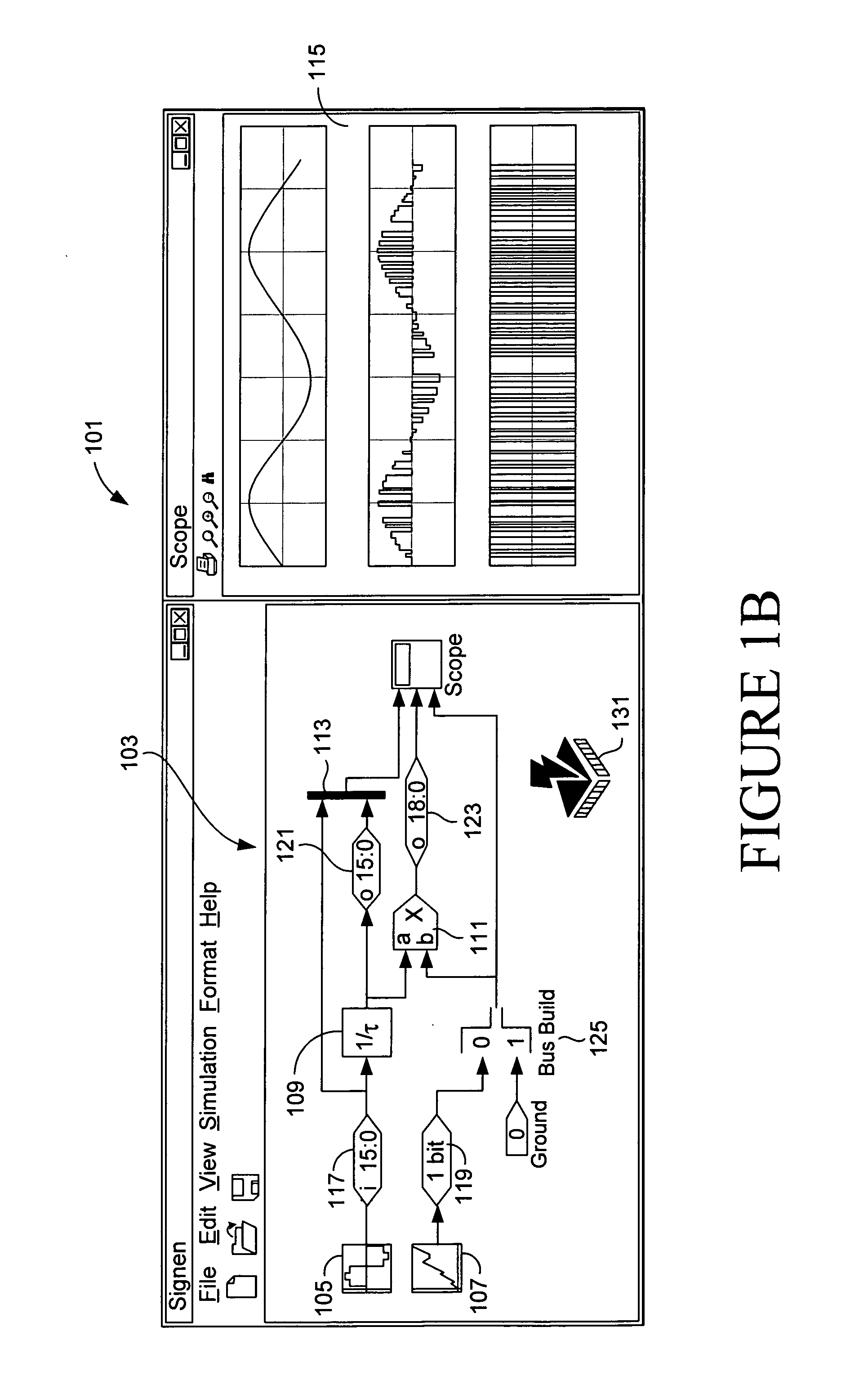
Some typical features of the conversion of a system level representation to an HDL representation will now be described. When a user enters a design in a system level interface, the modules of that interface are provided with both a graphical representation and a model representation. The model representation is employed during system level simulation of the design. The model representation provides a functional or behavioral description of the particular module with which it is associated. Typically, the model representation is provided in a compilable or interpretive language such as C++ or MATLAB's M Script. In the context of a Simulink system level simulator, the various modules and their model representation are packaged in an “mdl” file containing the necessary information to perform a simulation of the user-entered design when the model representations are executed.

In the context of this invention, embedded logic analyzer nodes preferably include a very simp...


PUM


Abstract

An electronic design automation system merges embedded logic analyzer technology with system level design and analysis technology. Embedded logic analyzers provide hardware to allow board-level signal capture and subsequent analysis of test devices programmed with a hardware design generated using electronic design automation. System level environments provide interactive tools for entering, modeling, simulating and analyzing multi-domain systems such as DSP designs. Typically, a user enters a system level design as a block diagram, including embedded logic analyzer blocks. The user inserts such blocks at nodes in the design where he or she wishes to capture signals to verify the design.

Description

AUTHORIZATIONA portion of the disclosure of this patent document contains material which is subject to copyright protection. The copyright owner has no objection to the facsimile reproduction by anyone of the patent document or the patent disclosure, as it appears in the Patent and Trademark Office patent file or records, but otherwise reserves all copyright rights whatsoever.BACKGROUNDThis application relates to embedded logic analyzers and system level design environments. More particularly, the invention relates to system level design interfaces that allow users to insert embedded logic analyzers in electronic designs and then analyze outputs of such logic analyzers using system level analysis tools.Simulink® (available from The MathWorks, Inc. of Natick, Mass.) and similar system level environments allow users to design and simulate Digital Signal Processing Systems (DSPs) and other electronic devices at the algorithm level. In a graphical user interface window, users enter logi...

Claims


Application Information

Patent Timeline
IPC IPC(8): G06F9/455
CPCG06F17/5022G06F2217/14G06F30/33G06F30/333
Inventor D'SOUZA, MARIAMOLSON, PHILIPPE
Owner ALTERA CORP
Learn More