Turbine system and method for extracting energy from waves, wind, and other fluid flows
a turbine system and fluid flow technology, applied in the direction of wind energy generation, machines/engines, wind energy generation, etc., can solve the problems of increasing devices that do not provide for capturing wave potential energy, and are exposed to a limited amount of wave power, so as to reduce manufacturing and operating costs, reduce energy loss, and increase power generation capacity
- Summary
- Abstract
- Description
- Claims
- Application Information
AI Technical Summary
Benefits of technology
Problems solved by technology
Method used
Image
Examples
first embodiment
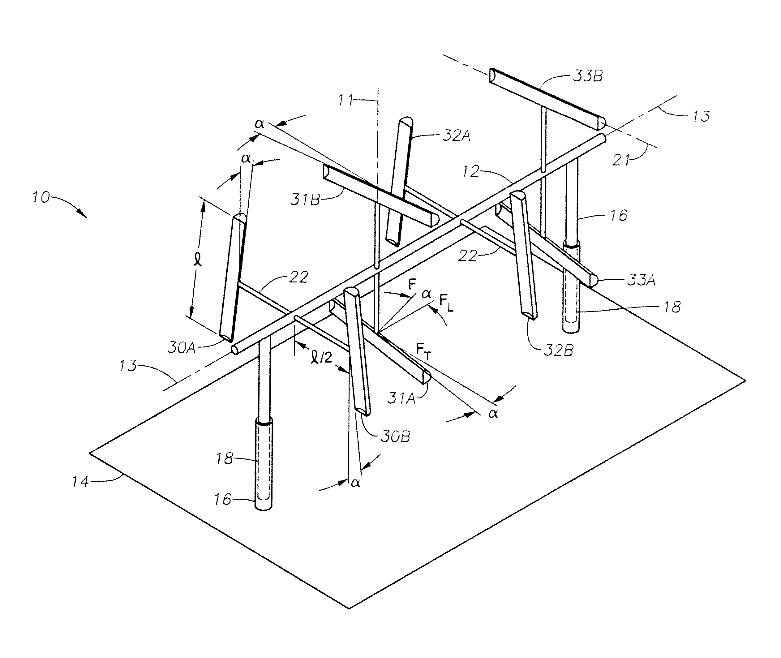
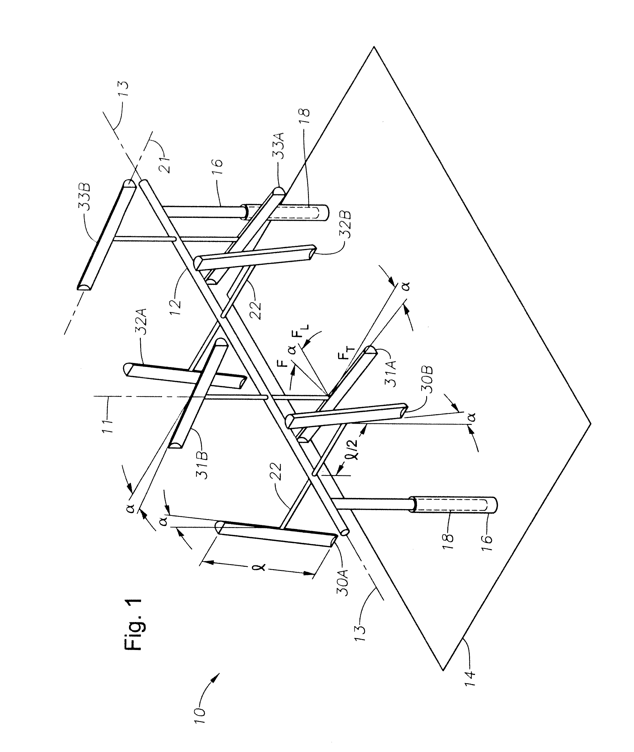
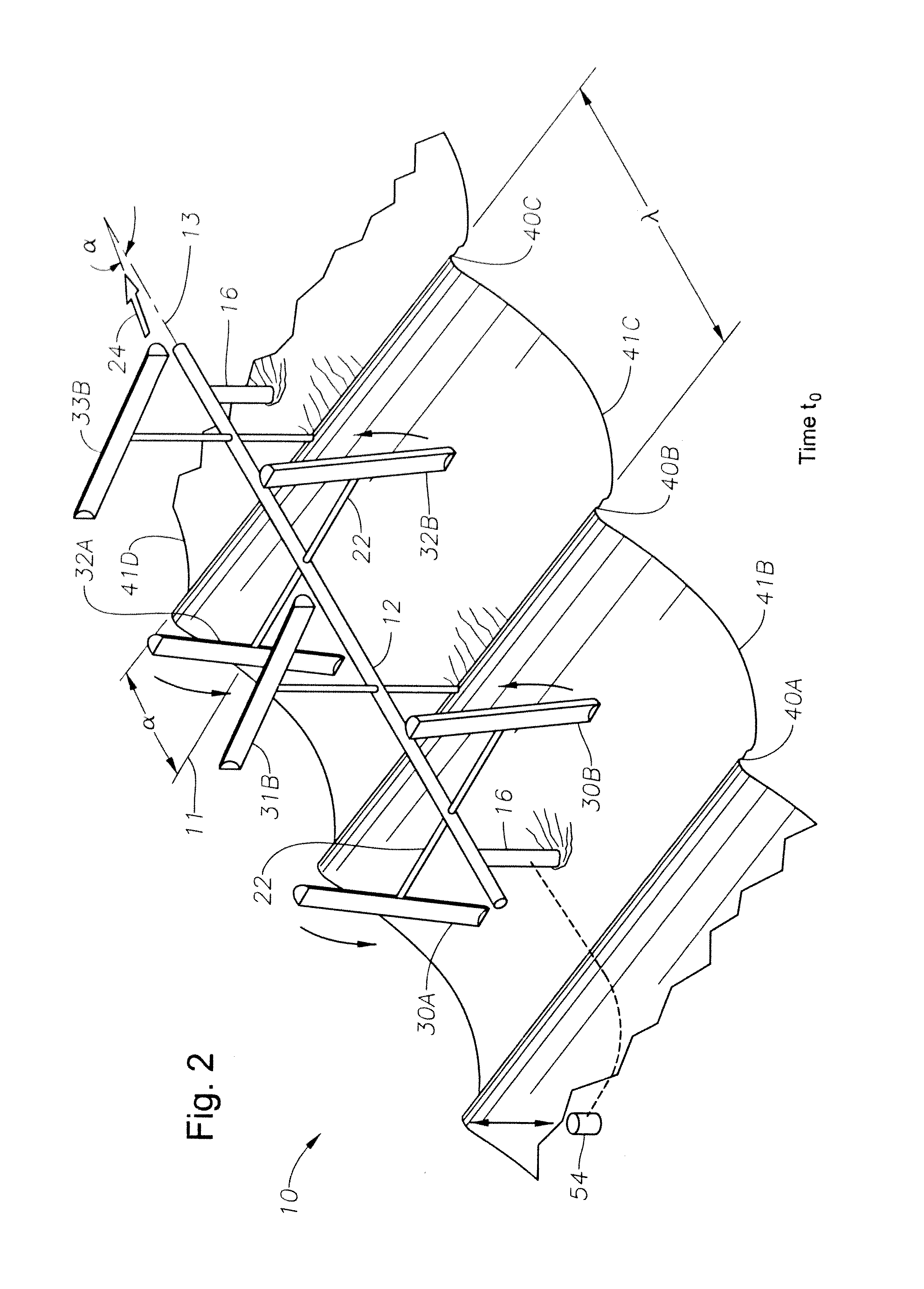
[0057]FIG. 5 is a cross section view, taken transversely to bucket longitudinal axis 21, of a bucket 30′ of wave turbine 10 according to the invention. Bucket 30′ has an open box-like scoop 60 formed of an arcuate back wall 62 of length l (FIG. 1) sandwiched between two endplates 64. Scoop 60 is designed to extract wave kinetic energy by capturing a portion of the wave therein. Bucket 30′ also includes a drum 66 that is preferably formed of a cylindrical wall 68, also of length l sandwiched between two endplates 70. Drum 66 is watertight, sealed from the ocean environment, and filled with air or foam for positive buoyancy. As bucket 30′ becomes submerged in a wave crest, its positive buoyancy creates an upward lifting force that converts a portion of the wave's potential energy to bucket kinetic energy for rotating the turbine drive shaft. A number of ribs 72 are longitudinally intervaled and connected between scoop 60 and drum 66 for connecting the two members and creating strength...
second embodiment
[0058]FIG. 6 is a cross section view, taken transversely to bucket longitudinal axis 21 along lines 6-6 of FIG. 4, of bucket 31B of wave turbine 10 according to the invention. FIG. 7 is an exploded diagram of FIG. 6. Referring to FIGS. 6-7 collectively, bucket 31B has an open box-like scoop 80 formed of an arcuate double-hull wall 81 of length l (FIG. 1). The double-hull wall 81 is formed of an inner arcuate wall 82, which forms the back wall of scoop 80, and an outer arcuate wall 84. Double-hull wall 81 is sandwiched between two endplates 86. Scoop 80 is designed to extract wave kinetic energy by capturing a portion of the wave therein. Double-hull wall 81 defines a watertight cavity 88, which is sealed from the ocean environment and filled with air or foam for positive buoyancy. As bucket 31B becomes submerged in a wave crest, its positive buoyancy creates an upward lifting force that converts a portion of the wave's potential energy to bucket kinetic energy for rotating the turbi...
PUM
 Abstract
Description
Claims
Application Information
 - R&D
- Intellectual Property
- Life Sciences
- Materials
- Tech Scout
- Unparalleled Data Quality
- Higher Quality Content
- 60% Fewer Hallucinations
Browse by: Latest US Patents, China's latest patents, Technical Efficacy Thesaurus, Application Domain, Technology Topic, Popular Technical Reports.
© 2025 PatSnap. All rights reserved.Legal|Privacy policy|Modern Slavery Act Transparency Statement|Sitemap|About US| Contact US: help@patsnap.com


