
Coated cutting insert and manufacturing method thereof

a cutting insert and coating technology, applied in the direction of cutting inserts, natural mineral layered products, turning machine accessories, etc., can solve the problems of difficulty in readily recognizing which cutting edge has been used, uneven use of cutting edges in the cutting process, and impairment of the appearance and surface smoothness of work materials after cutting, so as to prevent the problem of chipping and easy visual recognition

Active Publication Date: 2011-08-23
SUMITOMO ELECTRIC HARDMETAL CORP
View PDF25 Cites 18 Cited by
  • Summary
  • Abstract
  • Description
  • Claims
  • Application Information

AI Technical Summary

Benefits of technology

The present invention provides a coated cutting insert with an effective attention-getting function without impairing appearance or surface smoothness of a work material. The insert has a substrate with at least one surface serving as a rake face and another surface serving as a flank face. The indicating layer is formed on the part of the base layer that is exposed at the cutting edge. The base layer has compressive residual stress in the region where the indicating layer is formed. The method of manufacturing the coated cutting insert involves forming the base layer on the substrate, forming the indicating layer on the base layer, and removing the indicating layer in specific regions. The coated cutting insert can be used for various cutting processes such as drilling, end milling, milling, turning, working with a metal saw, working with a gear cutting tool, working with a reamer, working with a tap, and crankshaft pin milling.

Problems solved by technology

Specifically, the indicating layer adheres to the surface of the work material or the work material adheres to the indicating layer, with the result that an uneven cutting edge is used in the cutting process.
In such a case, appearance and surface smoothness of the work material after cutting is impaired.
In addition, if the indicating layer is provided on the flank face as in this coated cutting insert, it is difficult to readily recognize which cutting edge has been used when the insert is stored in a storage case or when the insert is placed on a workbench around a machine tool.
Usually, the flank face has an area smaller than the rake face, and therefore the insert is stored in the storage case or placed on the workbench with the rake face facing upward, which makes it difficult to observe the flank face.
Set aside the problem above, however, the coated cutting insert structured in such a manner has suffered the problem that chipping of the cutting edge is likely, and solving this problem has also been demanded.Patent Document 1: Japanese Patent Laying-Open No. 2002-144108Patent Document 2: International Publication No. 02 / 004156 Pamphlet

Method used


Image

  • Coated cutting insert and manufacturing method thereof
  • Coated cutting insert and manufacturing method thereof
  • Coated cutting insert and manufacturing method thereof

Examples


example 1

[0124]Raw material powders having a composition of 87 mass % WC, 2.0 mass % TiC, 2.0 mass % TaC, 1.0 mass % NbC, and 8.0 mass % Co were pressed, and successively sintered for one hour at a temperature of 1400° C. in a vacuum atmosphere. Thereafter, the resultant sintered object was subjected to planar polishing treatment and cutting edge treatment for the cutting edge using SiC brush (honing of a width of 0.05 mm from the side of rake face), thus fabricating an insert made of cemented carbide in a shape the same as that of cutting insert CNMG120408N-UX (manufactured by Sumitomo Electric Hardmetal Corp.). This insert was employed as the substrate. This substrate had the beta (β) removal layer formed on the surface to a thickness of 15 μm, and had 2 rake faces and 4 flank faces. The rake face and the flank face continued to each other with the cutting edge (being an imaginary ridge, because of the cutting edge treatment as above) lying therebetween. There were eight cutting edges in t...

example 2

[0177]Raw material powders having a composition of 88 mass % WC, 2.0 mass % TaC, and 10.0 mass % Co were pressed, and successively sintered for one hour at a temperature of 1400° C. in a vacuum atmosphere. Thereafter, the resultant sintered object was subjected to planar polishing treatment and cutting edge treatment for the cutting edge using SiC brush (honing of a width of 0.05 mm from the side of rake face), thus fabricating an insert made of cemented carbide in a shape of cutting insert ISO model number SPGN120408. This insert was employed as the substrate. This substrate did not have the beta (β) removal layer formed on the surface, and had 2 rake faces and 4 flank faces. The rake face and the flank face continued to each other with the cutting edge (being an imaginary ridge, because of the cutting edge treatment as above) lying therebetween. There were eight cutting edges in total.

[0178]Layers listed below were successively formed on the entire surface of the substrate with kn...


PUM

PropertyMeasurementUnit
widthaaaaaaaaaa
widthaaaaaaaaaa
temperatureaaaaaaaaaa

Abstract

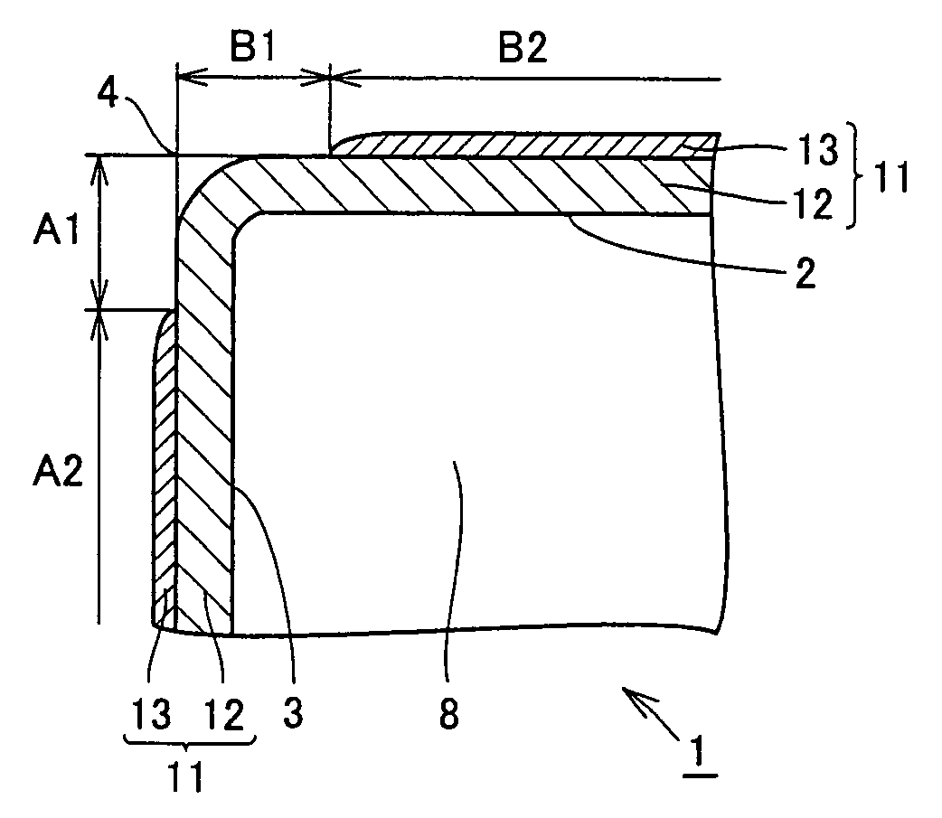
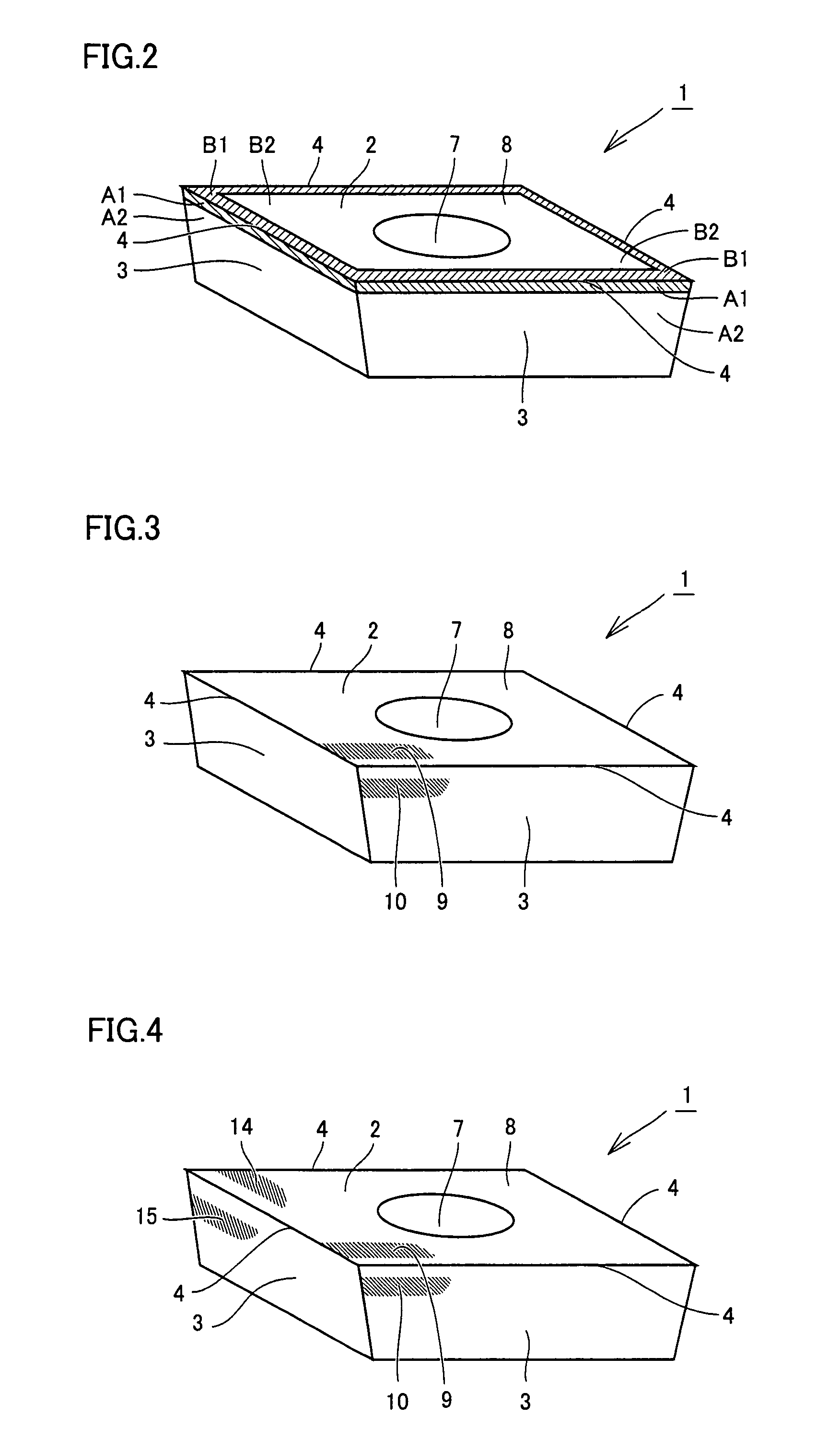
A coated cutting insert according to the present invention includes a base layer formed on a substrate and an indicating layer formed on a part of the base layer. The indicating layer is formed on a flank face, on the base layer on the entire surface or a part of a region A2 except for a specific region A1, and on a rake face, on the base layer on the entire surface or a part of a region B2 except for a specific region B1. In the region A1 and the region B1, the base layer is exposed at the surface, and has compressive residual stress in one or both of the region A1 and the region B1.

Description

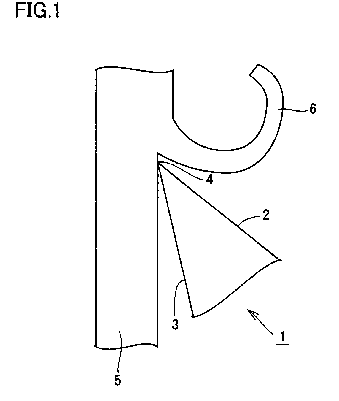
RELATED APPLICATIONS[0001]This application is the U.S. National Phase under 35 U.S.C. §371 of International Application No. PCT / JP2006 / 305649, filed on Mar. 22, 2006, which in turn claims the benefit of Japanese Application No. 2005-095461, filed on Mar. 29, 2005, the disclosures of which Applications are incorporated by reference herein.TECHNICAL FIELD[0002]The present invention relates to a coated cutting insert used in a cutting tool for cutting process and to a manufacturing method thereof. More specifically, the present invention relates to a coated cutting insert particularly useful for drilling, end milling, milling, turning, working with a metal saw, working with a gear cutting tool, working with a reamer, working with a tap, and crankshaft pin milling, as well as to a manufacturing method thereof.BACKGROUND ART[0003]A tool for turning or a tool for milling includes a single coated cutting insert or a plurality of coated cutting inserts. As shown in FIG. 1, such a coated cut...

Claims


Application Information

Patent Timeline
Patent Type & Authority Patents(United States)
IPC IPC(8): B32B9/00
CPCB23B27/141B23C5/20C23C30/005B23B2200/085B23B2200/245B23B2200/3654B23B2224/28B23B2224/32Y10T407/27B23B2228/10B23B2260/144B23C2228/10B23B2224/36B23B27/14B23B51/00C23C14/08B23C5/16
Inventor OMORI, NAOYAOKADA, YOSHIOITOH, MINORUOKUNO, SUSUMUIMAMURA, SHINYA
Owner SUMITOMO ELECTRIC HARDMETAL CORP
Learn More