Apparatuses and methods for a level shifter with reduced shoot-through current

a technology of shoot-through current and level shifter, which is applied in the direction of pulse automatic control, logic circuit, pulse technique, etc., can solve the problems of increasing propagation delay and output slew rate, increasing supply voltage, and increasing output slew rate, etc., to achieve the effect of reducing the output slew rate, and reducing the shoot-through curren

Active Publication Date: 2011-08-23
INTEGRATED DEVICE TECH INC
View PDF9 Cites 18 Cited by
  • Summary
  • Abstract
  • Description
  • Claims
  • Application Information

AI Technical Summary

Problems solved by technology

This mode of switching may also inhibit the transition time thereby increasing propagation delay and output slew rate.
However, in high-voltage systems, (e.g., Vhigh is 30V or more) the supply voltage may become more of a problem as present high performance transistors may not have a gate oxide able to standoff such high-voltages.
As this standby current is reduced to lower power consumption, other parameters such as shoot-through current, propagation delay, and output slew rate may be adversely affected.

Method used


Image

  • Apparatuses and methods for a level shifter with reduced shoot-through current
  • Apparatuses and methods for a level shifter with reduced shoot-through current
  • Apparatuses and methods for a level shifter with reduced shoot-through current

Examples


Embodiment Construction

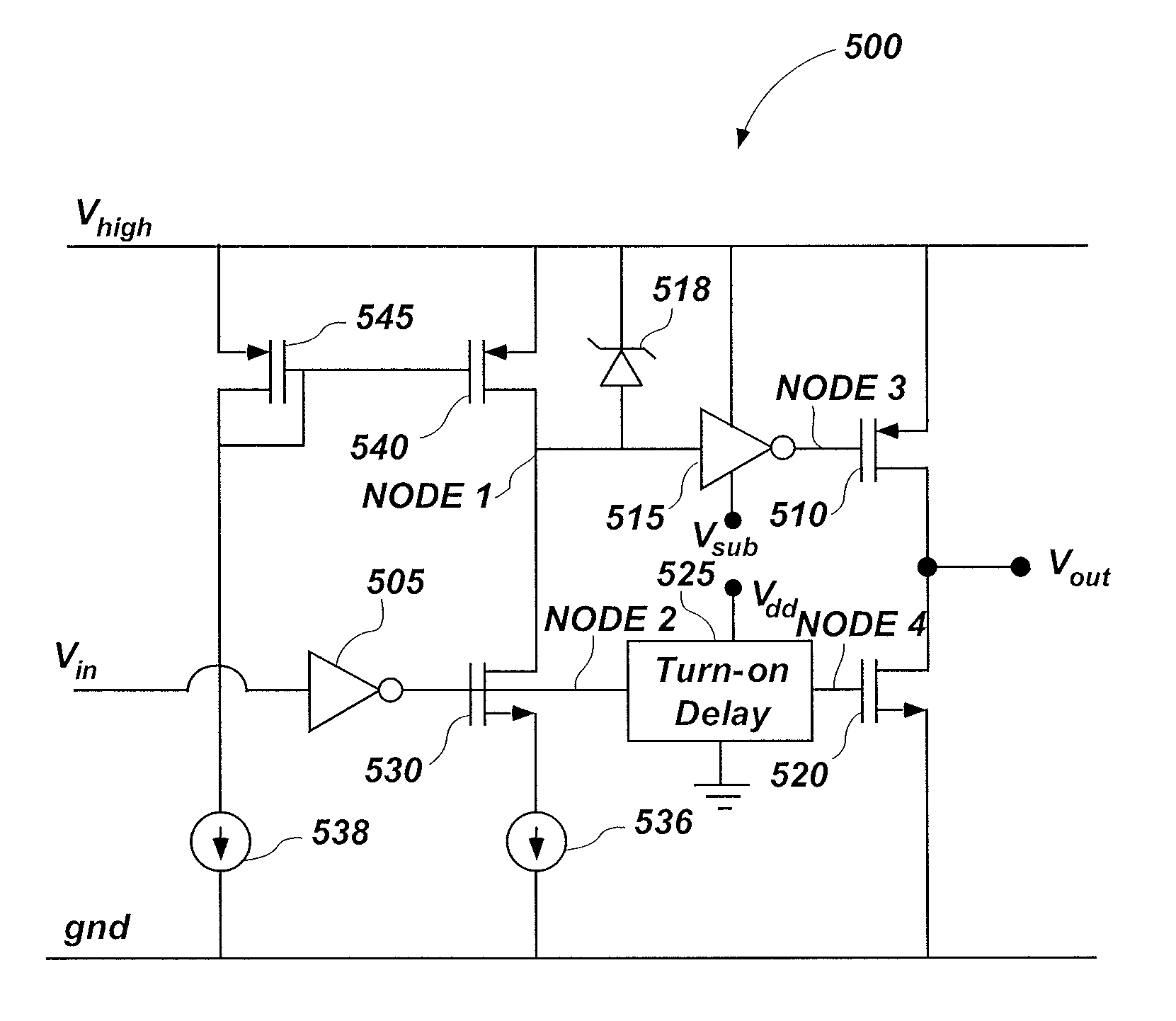
[0024]Embodiments of the present disclosure include apparatuses and methods for level-shifting. Although some examples used herein may describe level shifters implemented in TFT panels for LCDs, embodiments of the present disclosure should not be viewed as so limited. Rather, embodiments may be implemented as a driver of a load in many applications in which parameters such as high-voltage shifting, non-overlap timing, low shoot-through current, low standby current, or any combination thereof, may be desirable. Examples of such applications may include switching converters such as buck and boost converters, TFT level shifters, or other applications, which may require level-shifting from low-voltage digital control to high-voltage output signals.

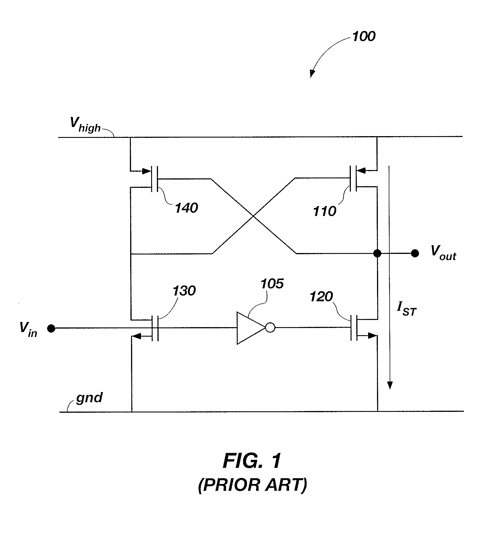
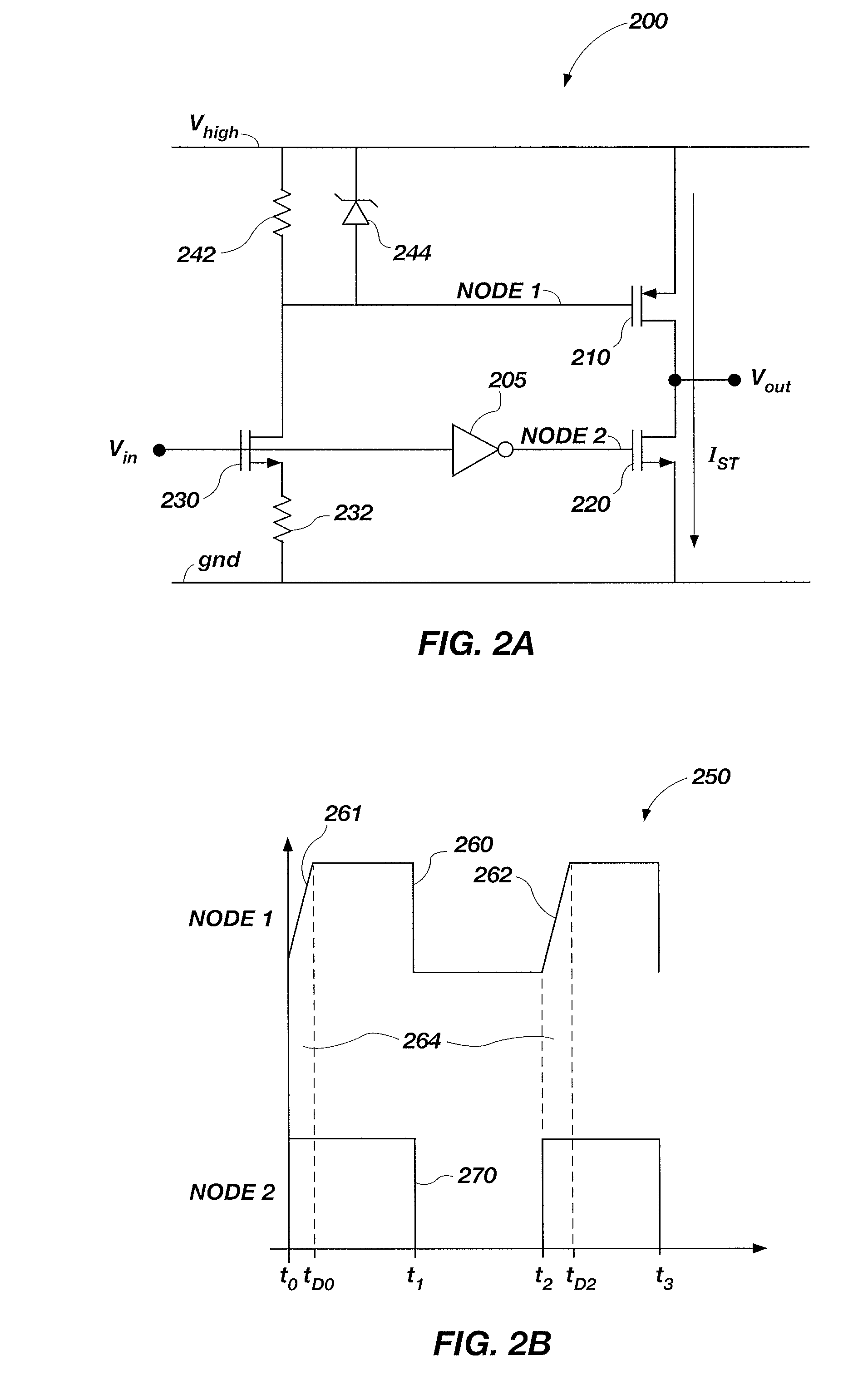
[0025]As previously discussed, level shifter 100 of FIG. 1 may not be suitable when the supply voltage exceeds the transistor maximum gate-to-source voltage. FIG. 2A illustrates a level shifter 200 which may be used when the supply voltage exc...


PUM


Abstract

A level-shifting circuit with reduced shoot-through current includes an output circuit comprising high-voltage devices with a pull-up circuit configured for pulling up a voltage on an output signal to a high voltage responsive to a high-side control signal. The output circuit may also include a pull-down circuit configured for pulling down the voltage on the output signal to a low voltage in responsive to a low-side control signal. The level-shifting circuit can also include a high-side inverting buffer operably coupled between an edge-controlled signal and the high-side control signal, and a low-side buffer configured for driving the low-side control signal responsive to an input signal. The level-shifting circuit may also include an edge-control buffer operably coupled between the input signal and the high-side inverting buffer and configured to generate the edge-controlled signal with a slow rise time relative to a fall time.

Description

TECHNICAL FIELD[0001]Embodiments of the present disclosure relate generally to voltage level-shifting and, more particularly, to apparatuses and methods related to high-voltage level shifters with reduced shoot-through current.BACKGROUND[0002]Level shift circuits (also referred to herein as level shifters) change the voltage level of a signal. For example, when an output voltage of a first circuit differs from an operating range of a second circuit, a level shifter is arranged between the first circuit and the second circuit, and the voltage level of the signal between the first and second circuits is adjusted. For example, in the driving circuitry for a liquid crystal display (LCD) panel, such as those using thin film transistors (TFT), signals having various voltages may be employed. In this case, signals having different voltages are generated from a common power supply and a level shift circuit is provided to adjust the levels of the signals between circuit blocks having differe...

Claims


Application Information

Patent Timeline
Patent Type & Authority Patents(United States)
IPC IPC(8): H03L5/00
CPCH03K19/0008H03K19/018521
Inventor BARROW, JEFFREY G.
Owner INTEGRATED DEVICE TECH INC
Why Eureka
Try Eureka