Eureka AIR delivers breakthrough ideas for toughest innovation challenges, trusted by R&D personnel around the world.

Optical amplification module and laser light source apparatus

a technology of optical amplification and laser light source, which is applied in the direction of electrical devices, fibre transmission, laser details, etc., can solve the problems of not being able to achieve both and the overall length of the ybdf becomes long. , to achieve the effect of effective suppression of photodarkening and efficient optical amplification

Inactive Publication Date: 2011-08-30
MEGAOPTO
View PDF8 Cites 1 Cited by
  • Summary
  • Abstract
  • Description
  • Claims
  • Application Information

AI Technical Summary

Benefits of technology

[0012]The present invention has been developed to eliminate the problems described above. It is an object of the present invention to provide an optical amplifier module and a laser light source apparatus comprising a structure for achieving effective suppression of photodarkening and efficient optical amplification.
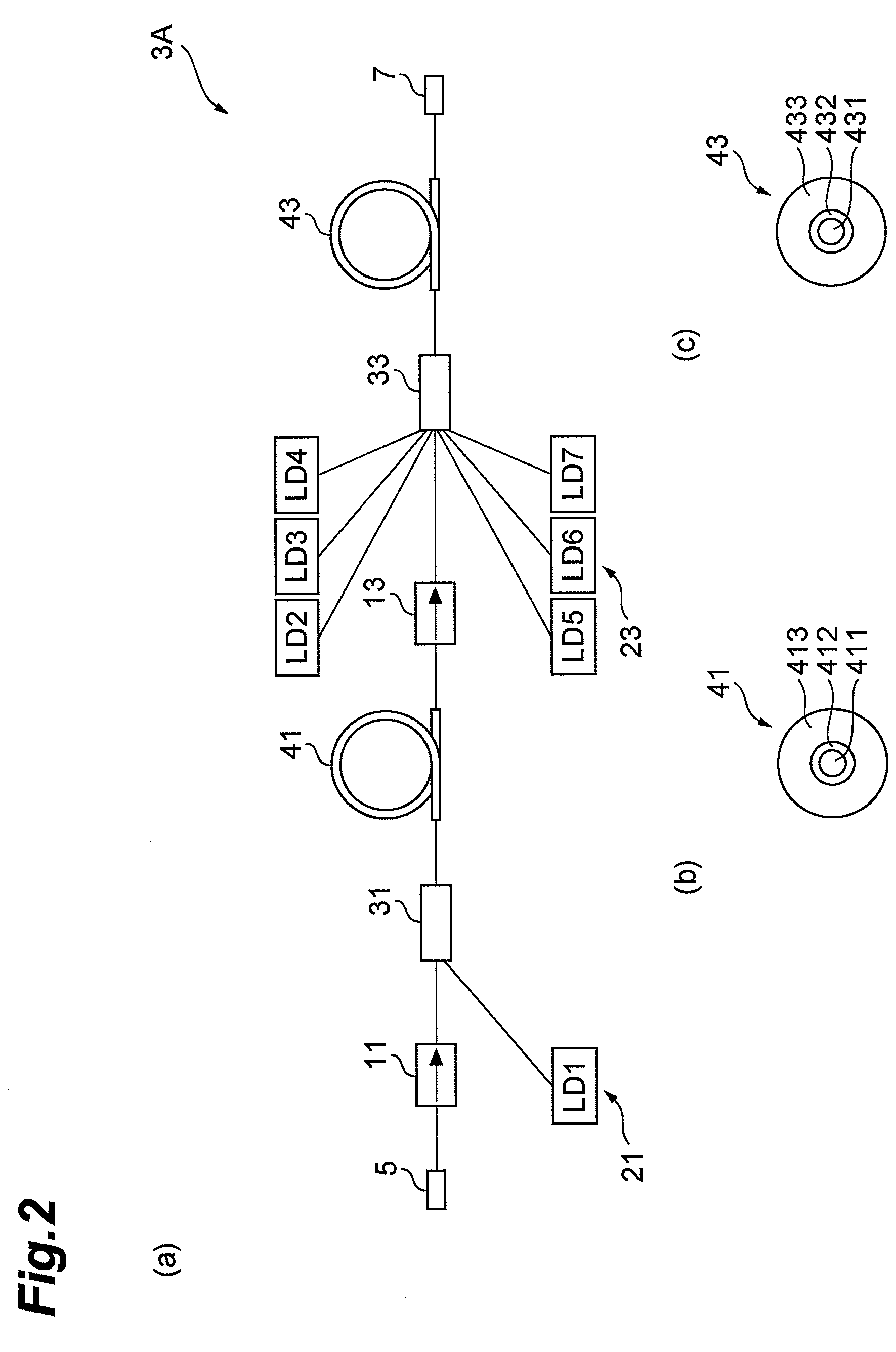
[0015]In the optical amplifier module according to the present invention which has a composition such as that described above, a second optical amplification waveguide including a ytterbium-doped second optical waveguide region which is co-doped with Al is provided in the portion where the population inversion ratio is low, and a first optical amplification waveguide including a ytterbium-doped first optical waveguide region which includes P is provided in the portion where the population inversion ratio is high. In this way, by disposing a second optical amplification waveguide which has a high pumping efficiency in the portion having a low population inversion ratio (the side of the amplified light output terminal) which is principal in determining the pumping efficiency of the optical amplifier module (the power ratio of the light to be amplified with respect to the inputted pumping power), it is possible to avoid deterioration in the pumping efficiency of the optical amplifier module.
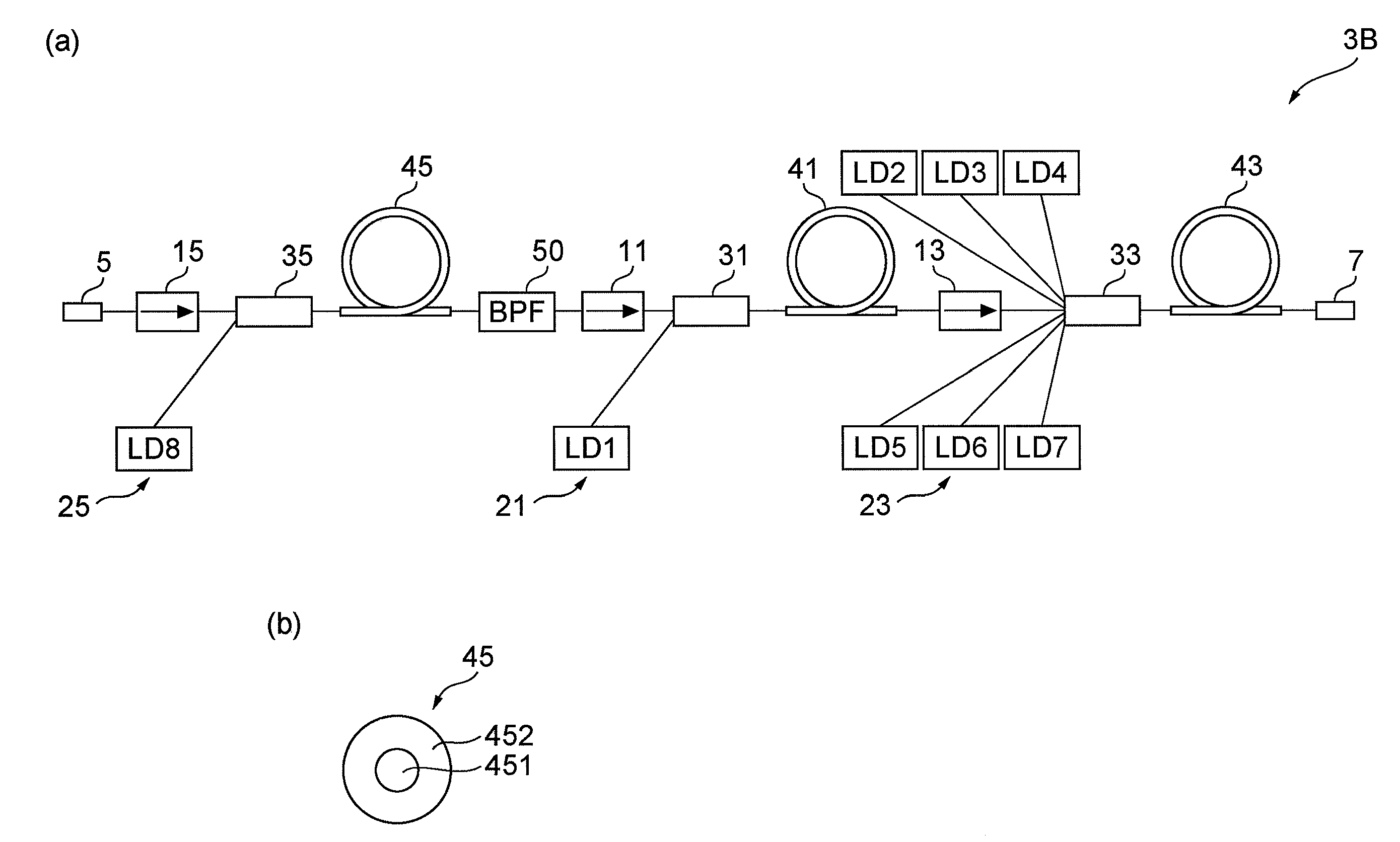
[0016]By disposing a first optical amplification waveguide which has a relatively low population inversion ratio in the portion where photodarkening is liable to occur due to a high population inversion ratio (the side of the input terminal of the light to be amplified), it is possible to suppress photodarkening effectively. Furthermore, the optical amplifier module relating to the present invention has a composition for amplifying the light to be amplified further in the second optical amplification waveguide, after it has been amplified in the first optical amplification waveguide. Therefore, the first optical amplification waveguide has low Amplified Spontaneous Emission (ASE). In an optical amplifier module which amplifies the light in multiple stages by means of a plurality of optical amplification waveguides arranged in series, as in the optical amplifier module according to the present invention, a wavelength selector element is normally disposed between the nearest-end optical amplification waveguide and the last-stage optical amplification waveguide, in order to remove noise components, such as ASE. However, in this optical amplifier module, since the light to be amplified is inputted to the first optical amplification waveguide which has low ASE, then it is possible to obtain similar beneficial effects to those of a case where a wavelength selector element is provided, without using a wavelength selector.
[0017]Since the light that has been amplified in the first optical amplification waveguide which has low ASE is further amplified in the second optical amplification waveguide which has high pumping efficiency, efficient amplification of the light to be amplified can be achieved. Consequently, In accordance with the optical amplifier module according to the present invention, it is possible to achieve both effective suppression of photodarkening and efficient optical amplification.
[0018]Furthermore, it is desirable to use respective ytterbium-doped optical fibers for the first optical amplification waveguide and the second optical amplification waveguide. By using easily procured YbDF for the first and second optical amplification waveguides in this way, the manufacture of the optical amplification waveguide having the composition described above is facilitated.
[0021]Desirably, the laser light source apparatus according to the present invention comprises an optical amplifier module having a structure such as that described above (an optical amplifier module according to the present invention) and a laser diode which outputs light to be amplified having a pulse width in the range of 1 ns to 100 ns and a central wavelength in the range of 1062 nm to 1072 nm. By means of this composition, it is possible to achieve effective suppression of photodarkening and efficient optical amplification, while setting the region of the central wavelength of the outputted laser light to around 1064 nm which is similar to that of existing YAG lasers.

Problems solved by technology

However, since these prior art technologies use a low-concentration TbDF, then the overall length of the YbDF becomes long, which is disadvantageous in terms of housing the element and reducing costs, and so on.
Consequently, there has been a problem in that it is not possible to achieve both effective suppression of photodarkening and efficient optical amplification.

Method used


Image

  • Optical amplification module and laser light source apparatus
  • Optical amplification module and laser light source apparatus
  • Optical amplification module and laser light source apparatus

Examples


first embodiment

of Optical Amplifier Module

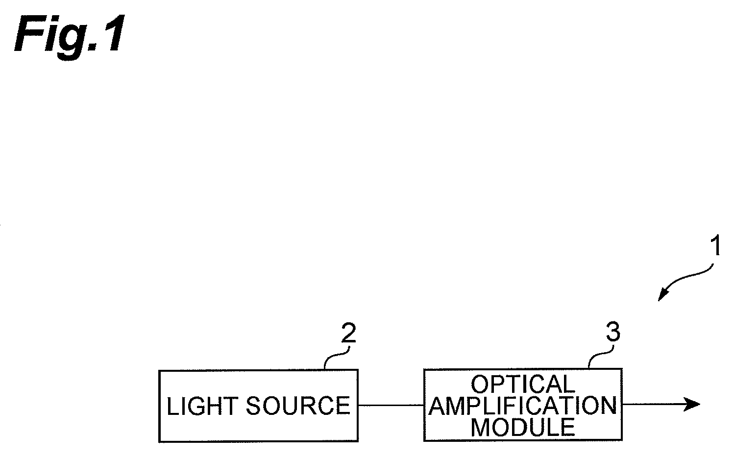
[0034]The optical amplifier module 3 amplifies the light to be amplified which is outputted from the laser light source 2. In the laser light source apparatus 1 (FIG. 1), the light to be amplified that is outputted from the laser light source 2 is outputted after being amplified by the optical amplifier module 3.

[0035]FIG. 2 is a diagram showing the composition of a first embodiment of an optical amplifier module according to the present invention. As shown in the area (a) of FIG. 2, the optical amplifier module 3A relating to the first embodiment inputs light to be amplified that is outputted from the laser light source 2, via an input terminal 5, and amplifies and then outputs this light to be amplified via the output terminal 7. More specifically, the optical amplifier module 3A comprises an input terminal 5 and an output terminal 7, and also comprises optical isolators 11, 13, pumping light source units (pumping units) 21, 23, an optical coupler 31, a ...

modification example

[0050]Next, a modification example of the optical amplifier module 3A relating to the first embodiment is described. The optical amplifier module relating to the modification example has a different composition of the first optical amplification waveguide 41, but the remainder of the composition is the same as the optical amplifier module 3A relating to the first embodiment shown in the area (a) of FIG. 2. The first optical amplification waveguide 41 according to the modification example is a Yb-doped fiber which is comprised of a silica glass as a main component and comprises a core region 411 (first waveguide region), a first cladding region 412 surrounding the core region 411 and a second cladding region 413 surrounding the first cladding region 412. Furthermore, at least a portion of the core region 411 is co-doped with ytterbium and P at 20 wt % concentration or above.

[0051]The optical amplifier module relating to the present modification only differs from the optical amplifier...

example 1

Practical Example 1

[0053]The fiber according to Practical Example 1 is a Yb-doped fiber (hereinafter referred to as “YbDF-A” below) which can be used as the first optical amplification waveguide 41 of the respective embodiments of the present invention. The YbDF-A is a Yb-doped fiber is comprised of a phosphate glass as a main component and includes 26.4 wt % of P and 0.8 wt % of Al, a core diameter of 10 μm, a first cladding diameter of 125 μm, a 1.8 dB / m non-saturated absorption of 915 nm-waveband pumping light, and a length of 8 m. Furthermore, the Yb weight concentration in the YbDF-A is 47000 wt-ppm.


PUM


Abstract

The present invention relates to an optical amplifier module, or the like, having a structure for enabling effective suppression of photodarkening and efficient optical amplification. The optical amplifier module comprises a first optical amplification waveguide which is comprised of a phosphate glass as a main component and includes a ytterbium-doped first optical waveguide region, a second optical amplification waveguide which is optically coupled to the first optical amplification waveguide and includes a ytterbium-doped second optical waveguide region which is co-doped with aluminum, and pumping light source units which supply pumping light respectively to the first optical amplification waveguide and the second optical amplification waveguide. The light to be amplified, having inputted to the first optical amplification waveguide, is amplified only once by means of the pumping light, in each of the first optical amplification waveguide and the second optical amplification waveguide.

Description

BACKGROUND OF THE INVENTION[0001]1. Field of the Invention[0002]The present invention relates to an optical amplifier module, which amplifies light to be amplified, and a laser light source apparatus comprising an optical amplifier module of this kind.[0003]2. Related Background Art[0004]Laser light sources which output light having a small spot size are required in industries such as ultrafine processing. In order to achieve practical use of a laser light source of this kind in an industrial application, and in particular, the processing of semiconductors and electrical components, it is necessary to shorten the pulse and raise the output of the laser light. In other words, it is necessary to achieve a laser light source having a pulse width of the nanosecond order which outputs light having a peak power exceeding a kW.[0005]In order to achieve a laser light source which outputs light having a small spot size, a laser light source of a type in which the actual optical amplification...

Claims


Application Information

Patent Timeline
Patent Type & Authority Patents(United States)
IPC IPC(8): H01S3/13
CPCH01S3/2316H01S3/1618H01S3/1693H01S3/176H01S3/175
Inventor KAKUI, MOTOKI
Owner MEGAOPTO
Why Eureka
Eureka Blog
Learn More