
Camcover oil separator

a technology of camouflage and oil separator, which is applied in the direction of lubrication of auxiliaries, combustion engines, casings, etc., can solve the problems of consuming a significant amount of the limited space available, degrading engine emission quality, and increasing net oil consumption, so as to reduce manufacturing costs and work more efficiently, the effect of reducing manufacturing costs

Inactive Publication Date: 2011-09-06
FORD GLOBAL TECH LLC
View PDF8 Cites 5 Cited by
  • Summary
  • Abstract
  • Description
  • Claims
  • Application Information

AI Technical Summary

Benefits of technology

The patent describes an oil separator for an internal combustion engine that separates oil mist from blow-by gas. The oil separator is mounted on the cylinder head and includes a camcover and a baffle positioned between the camcover and the cylinder head. The baffle has multiple through-holes that allow for multiple impacts and repetitive oil separation. The oil separator can be easily installed in limited space and reduces the need for oil drain valves and paths. The technical effects of the oil separator include improved oil separation efficiency, reduced oil consumption, and improved engine performance.

Problems solved by technology

However, combustion of the oil may cause the net oil consumption to increase, as well as degrade engine emission quality.
However, the inventors have recognized several issues with such an oil separator.
As one example, the distinct chambers and the related partition walls consume a significant amount of the limited space available above the cylinder head in the engine compartment.
For example, in a turbocharged V-6 engine operating with a direct injection of gasoline, the configuration of the engine may result in very limited space, particularly above the cylinder heads on the left hand bank.
The spatial constraints may not allow an oil separator with the configuration of '858 to be mounted.
As such, this may lead to a reduction in oil separation efficiency in the engine, thereby degrading overall engine oil consumption and exhaust emission levels.
In other embodiments, the through-holes may be offset such that there may be substantially no overlap, thereby causing oil separation by multiple and repetitive impacts.

Method used


Image

  • Camcover oil separator
  • Camcover oil separator
  • Camcover oil separator

Examples


Embodiment Construction

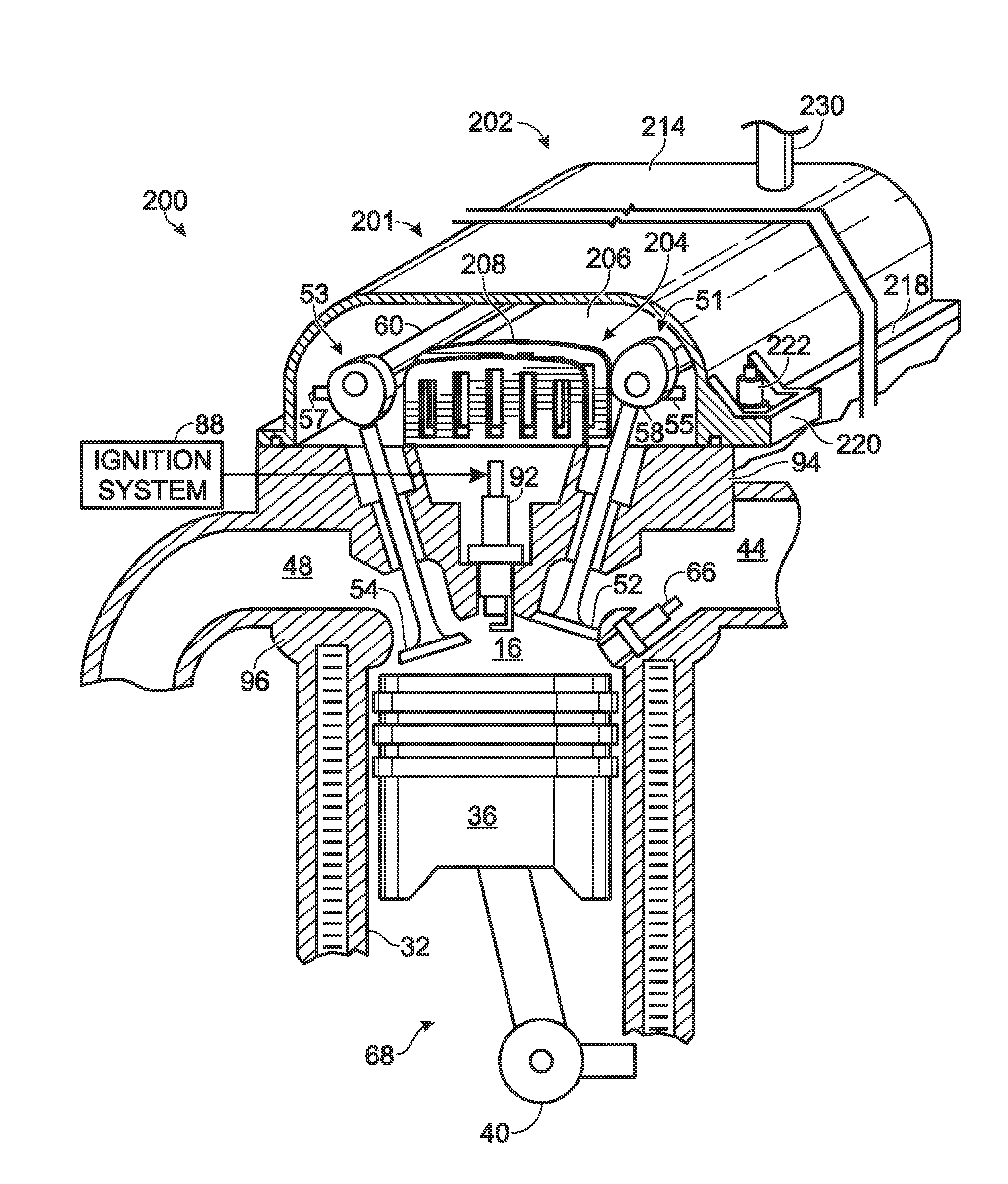
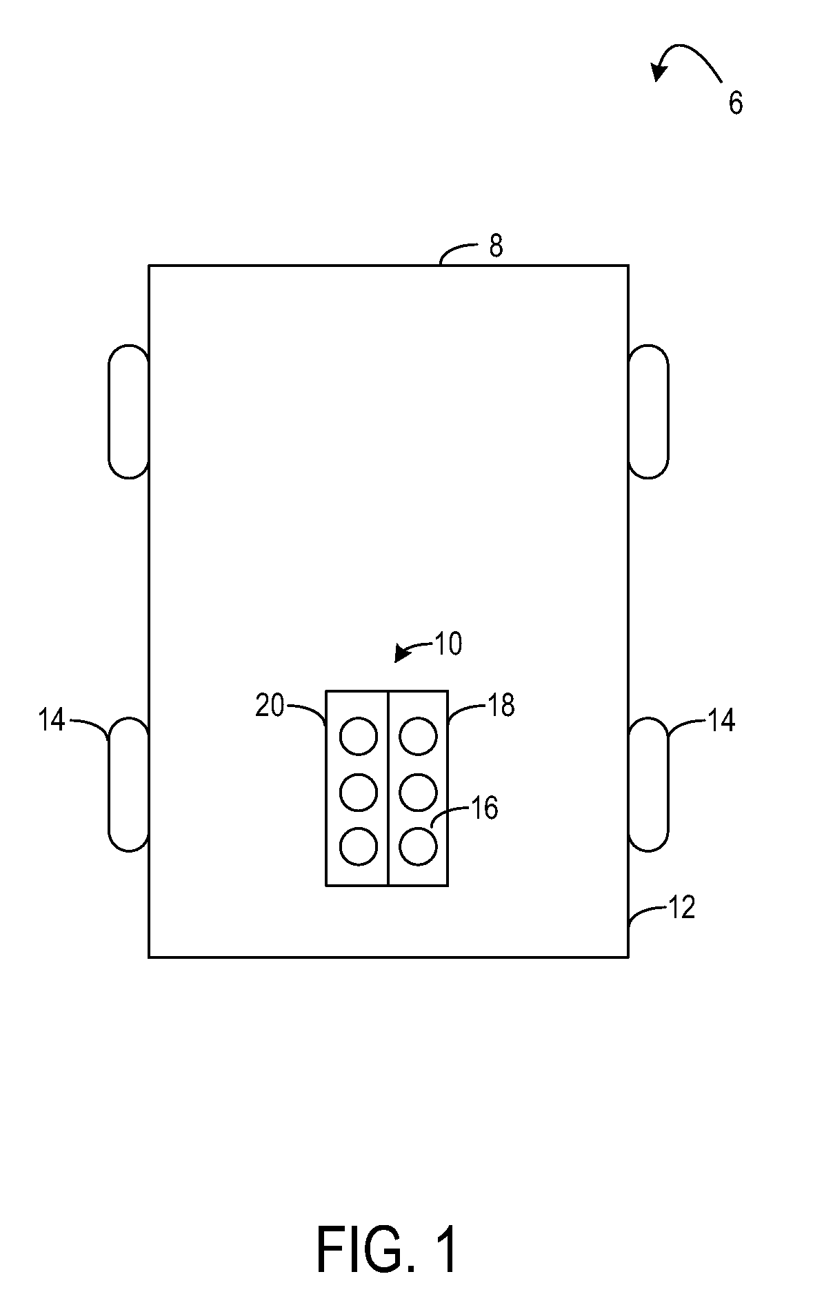
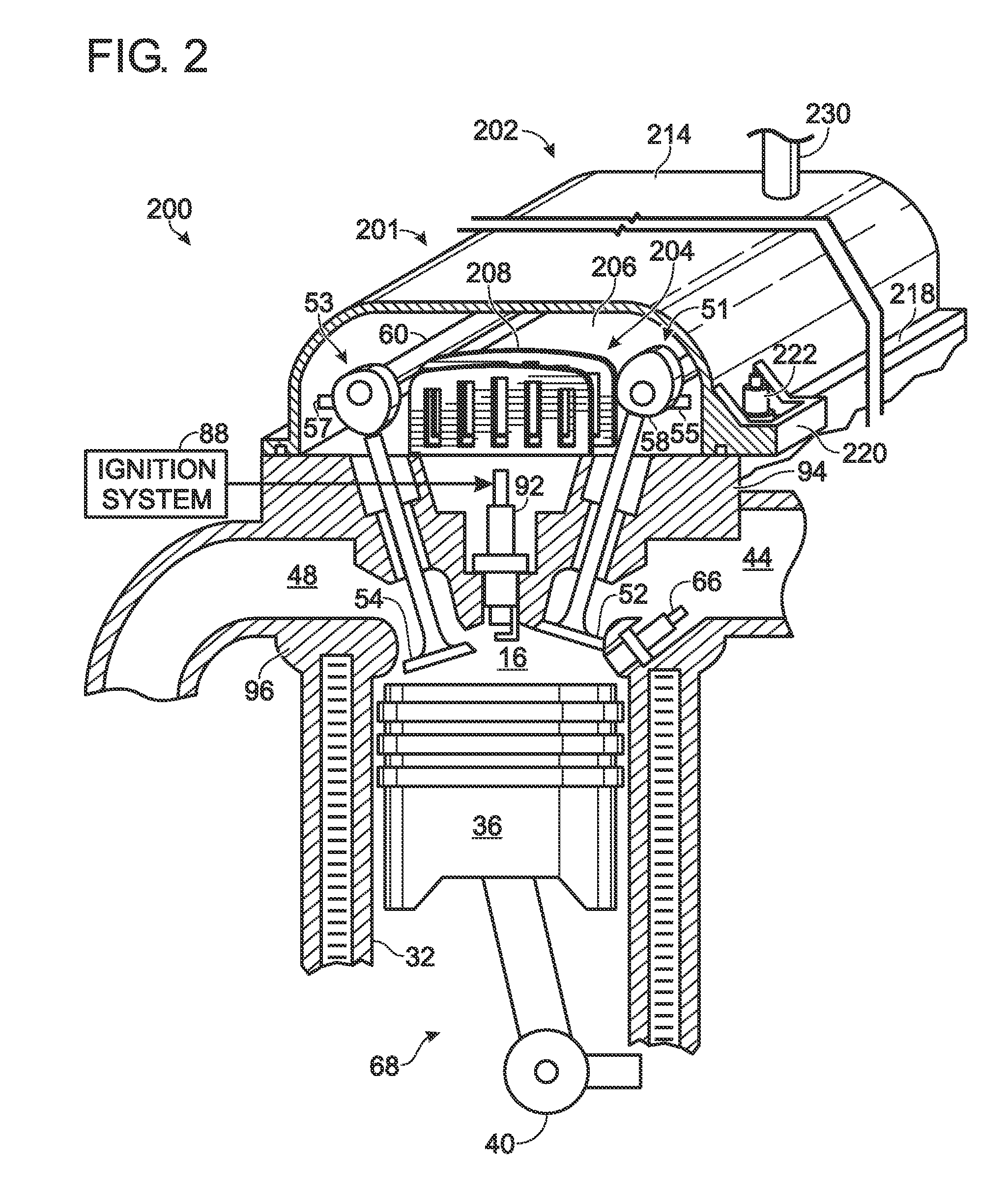
[0014]The following description relates to a system for separating oil from blow-by gas in an engine of a vehicle as shown in FIG. 1. The oil separator of the present disclosure is mounted inside an internal combustion engine, on top of a cylinder head, to substantially envelop a camshaft assembly, as shown in FIG. 2. As shown in FIG. 3, the oil separator may include at least two components, viz. an upper camcover and a lower baffle plate assembly. The oil separator may further employ a plurality of projections, or baffles, as illustrated with reference to FIGS. 3-4, to create a tortuous path for the blow-by vapors that are trapped in an oil separation chamber created by the oil separator. While passing through the tortuous path, the oil is separated from the mist by multiple-impaction. The separated oil is returned to the camshaft assembly for lubricating the rotating cam lobes, camshaft and / or the valve assembly. The baffles may be tuned to different engines based on the desired o...


PUM


Abstract

Systems are provided for separating oil from blow-by gases in an internal combustion engine. In one example, a system comprises a camcover configured to be mounted on a cylinder head, and a baffle positioned between the camcover and the cylinder head. The baffle may include at least a first and a second baffle plate, the first baffle plate including a first through-hole on a first face of the first baffle plate, the second baffle plate including a second through-hole on a second face of the second baffle plate. Further, the first and second faces may be positioned opposite one another, and offset such that the first and second through-holes are not fully overlapping.

Description

FIELD[0001]The present application relates to an oil separator provided in an internal combustion engine to separate oil from blow-by gases.BACKGROUND AND SUMMARY[0002]When an air-fuel mixture is combusted in an engine combustion chamber, a small portion of the combusted gas may enter the engine crankcase through the piston rings. This gas is referred to as blow-by gas. To prevent this untreated gas from being directly vented into the atmosphere, a crankcase ventilation system is provided between the higher pressure crankcase and the lower pressure intake manifold to allow the blow-by gas to flow from the crankcase into the intake manifold and be mixed with fresh air. From here, the gas may be re-inducted into the combustion chamber for re-combustion.[0003]Engine lubrication oil used to lubricate moving parts of the engine is present in the crankcase during normal engine operation. The high pressure in the crankcase causes some of the lubricating oil to be suspended in a mist form. ...

Claims


Application Information

Patent Timeline
Patent Type & Authority Patents(United States)
IPC IPC(8): F01M9/10F02B25/06
CPCF01M13/0416F01M2013/0433F01M2013/0461
Inventor NARAYANAKUMAR, ANANTHWEAVER, COREY
Owner FORD GLOBAL TECH LLC
Learn More