
Switching power supply with pulse frequency modulation control

a technology of pulse frequency modulation and switching power supply, which is applied in the direction of electric variable regulation, process and machine control, instruments, etc., can solve the problems of lowering the conversion efficiency, and large smoothing capacitor c/sub>o /sub> is hazardous for reducing the size so as to improve the conversion efficiency and improve the reliability of the switching power supply. , the effect of improving the conversion efficiency

Active Publication Date: 2011-09-06
FUJI ELECTRIC CO LTD
View PDF15 Cites 5 Cited by
  • Summary
  • Abstract
  • Description
  • Claims
  • Application Information

AI Technical Summary

Benefits of technology

[0056]According to the first through fourth aspects of the invention, the output voltage is controlled at a constant value without setting the winding ratios of the transformers to be small. Therefore, diodes exhibiting a low breakdown voltage may be used with no problem and the conversion efficiency is improved.
[0057]According to the fifth aspect of the invention, the minimum frequency set for preventing current leading mode from causing is set easily and the reliability of the switching power supply is improved.
[0058]According to the sixth aspect of the invention, the switching frequency is prevented from rising under a light load, the exciting current of the transformer is suppressed at a low value, and the conversion efficiency is improved independently of the load weight.
[0059]According to the seventh aspect of the invention, the magnetic flux amplitude under a heavy load is suppressed to be small and the core losses are reduced.

Problems solved by technology

Since the forward voltage drop across a diode becomes larger as the breakdown voltage of the diode becomes higher, more losses are caused in the diode, lowering the conversion efficiency of the switching power supply.
During the period described above, the effective values of the currents flowing through the transformer secondary windings and the diodes increase, lowering the conversion efficiency.
Large smoothing capacitor Co is hazardous for reducing the size of the switching power supply.
Therefore, it is very difficult to set the frequency Fmin, at which off-resonance is prevented from causing under all the unfavorable conditions including sudden change of the DC power supply voltage, sudden change caused in the load, and overload.

Method used


Image

  • Switching power supply with pulse frequency modulation control
  • Switching power supply with pulse frequency modulation control
  • Switching power supply with pulse frequency modulation control

Examples


Embodiment Construction

[0071]Now the invention will be described in detail hereinafter with reference to the accompanied drawings which illustrate the preferred embodiments of the invention.

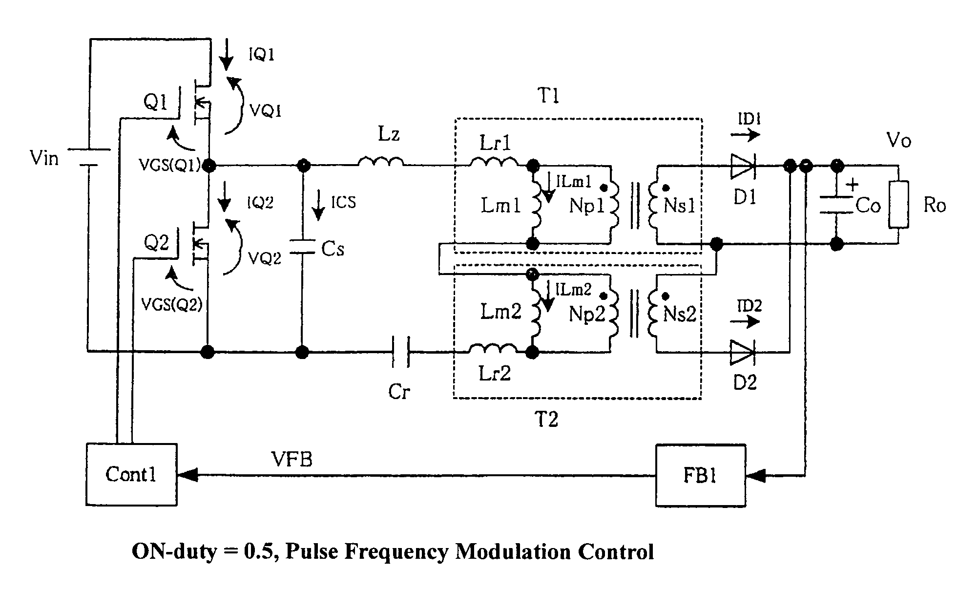
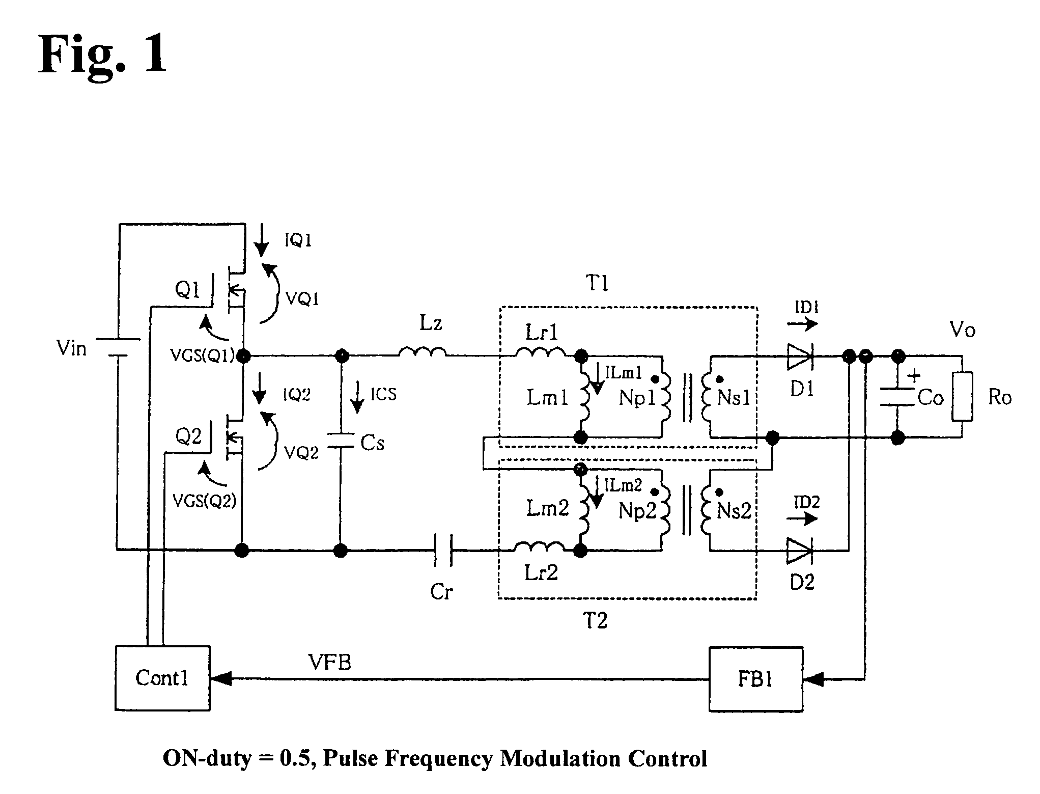
[0072]FIG. 1 is a block circuit diagram of a switching power supply according to a first embodiment of the invention. (The first aspect of the invention)

[0073]The switching power supply shown in FIG. 1 is different from the switching power supply shown in FIG. 5 in that a series resonance circuit is configured by the inductance components of transformers T1 and T2, inductance element Lz and capacitor Cr, and control circuit Cont1 conducts frequency control at the ON-duty set at 0.5 in the switching power supply shown in FIG. 1. Although the circuit configuration shown in FIG. 1 is the same as the circuit configuration shown in FIG. 5, any series resonance circuit is not formed in FIG. 5. Although there exists parasitic capacitance and internal inductance in parallel to MOSFETs Q1 and Q2 in FIG. 1 as well as in FIG. 5, ...


PUM


Abstract

A switching power supply exhibits high conversion efficiency and facilitates reducing the size thereof. The switching power supply includes a half-bridge circuit including a first series circuit formed of switching devices Q1 and Q2 and connected between the output terminals of a DC power supply; and a second series circuit connecting primary inductance Lr1 of transformer T1, primary inductance Lr2 of transformer T2 and capacitor Cr in series. The second series circuit is connected between the output terminals of the half-bridge circuit, and is made to conduct a series resonance operation. The switching devices Q1 and Q2 is controlled at the ON-duties of 0.5 for reducing the breakdown voltages of rectifying diodes D1 and D2 on the secondary side of transformers T1 and T2 and for improving the conversion efficiency of the switching device.

Description

BACKGROUND OF THE INVENTION AND RELATED ART STATEMENT[0001]The present invention relates to a switching power supply. Specifically, the invention relates to an isolation type DC-DC converter that obtains a DC output insulated from a commercial AC power supply.[0002]A DC output isolated from a commercial AC power supply is obtained usually with an isolation type DC-DC converter from an intermediate DC voltage obtained by rectifying and smoothing an AC voltage. In a power supply, to which the specifications on the higher harmonic of an input current are applied, an intermediate DC voltage is obtained from an AC power supply via a boost chopper circuit.[0003]It has been required for the switching power supply apparatuses to exhibit a high efficiency, to cause less noises, to be small in size, to be manufactured with low manufacturing costs, and to be very reliable. For meeting the demands described above, various circuit configurations have been proposed.[0004]FIG. 5 is a block circuit...

Claims


Application Information

Patent Timeline
Patent Type & Authority Patents(United States)
IPC IPC(8): H02M3/335H02M1/12
CPCH02M3/337Y02B70/1491H02M2001/0058Y02B70/1433Y02B70/10H02M1/0058H02M3/33571H02M3/01
Inventor NISHIKAWA, YUKIHIRO
Owner FUJI ELECTRIC CO LTD
Learn More