Photomask manufacturing method

a manufacturing method and mask technology, applied in the field of photomask manufacturing methods, can solve the problems of difficult automatic reading of identification markers using sensors, difficult to automate the photomask manufacturing process, and difficult to manage mask blanks, etc., and achieve the effect of secure detection

Active Publication Date: 2011-09-20
HOYA CORP
View PDF7 Cites 4 Cited by
  • Summary
  • Abstract
  • Description
  • Claims
  • Application Information

AI Technical Summary

Benefits of technology

[0008]It is therefore an object of this invention to provide a photomask manufacturing method that can solve the above-mentioned problems.
[0022]With this structure, it is possible to properly manage the orientation of the mask blank, for example. Accordingly, it is possible to prevent the orientations of end faces, each formed with an identification marker, of mask blanks from varying from each other and thus to securely detect the identification marker using the sensor. This makes it possible, for example, to properly automate the photomask manufacturing process. Further, it is possible to properly carry out the rotation of the mask blank and thus to properly form the mask pattern while avoiding the defect. This makes it possible to improve the manufacturing yield of photomasks.
[0028]According to Structure 2, even if, for example, the mask blank is rotated anyway before performing the exposure / writing, the mask blank can be oriented in the fixed direction thereafter. This makes it possible, for example, to more properly prevent the orientations of end faces, each formed with an identification marker, of mask blanks from varying from each other. Therefore, for example, when reading the identification marker in a step subsequent to the orientation restoration step, it is possible to securely detect the identification marker using a sensor. This makes it possible, for example, to more properly automate the photomask manufacturing process.
[0033]According to Structure 3, it is possible, for example, to rotate the photomask before a mask inspection of the photomask using the mask inspection apparatus so as to agree with the orientation of the mask blank at the time of the exposure / writing of the mask pattern. This makes it possible, for example, to properly collate the mask pattern thin film after the etching with the inspection pattern data in the mask inspection apparatus.
[0036]According to Structure 4, the photomask after the mask inspection can be oriented in the fixed direction, for example. This makes it possible, for example, to more properly prevent the orientations of end faces, each formed with an identification marker, of photomasks from varying from each other. This makes it possible, for example, to more properly automate the photomask manufacturing process.
[0037]According to this invention, based on defect information of a mask blank in which the position of a defect is specified using an identification marker as a reference, the placing orientation (writing direction) of the mask blank in an exposure / writing apparatus can be automatically controlled using a rotating apparatus so that the layout or arrangement of a mask pattern to be transferred to a mask pattern thin film is not adversely affected by the defect. This makes it possible to solve the problem of human error otherwise caused by manually rotating the orientation of the mask blank or a photomask produced therefrom. Further, even without using the method of providing an identification marker on all end faces of a substrate, the orientation of the mask blank or the photomask can be rotation-controlled using the rotating apparatus and thus the identification marker can be securely detected using a sensor.

Problems solved by technology

As a result, the orientation of an end face formed with an identification marker differs per mask blank and thus it is difficult to manage the mask blanks.
Further, if the orientations of the end faces, each formed with the identification marker, of the mask blanks vary from each other, it is difficult to automatically read the identification markers using a sensor, for example, in a photomask manufacturing process.
As a result, for example, there is also a possibility that it becomes difficult to automate the photomask manufacturing process.

Method used


Image

  • Photomask manufacturing method
  • Photomask manufacturing method
  • Photomask manufacturing method

Examples


Embodiment Construction

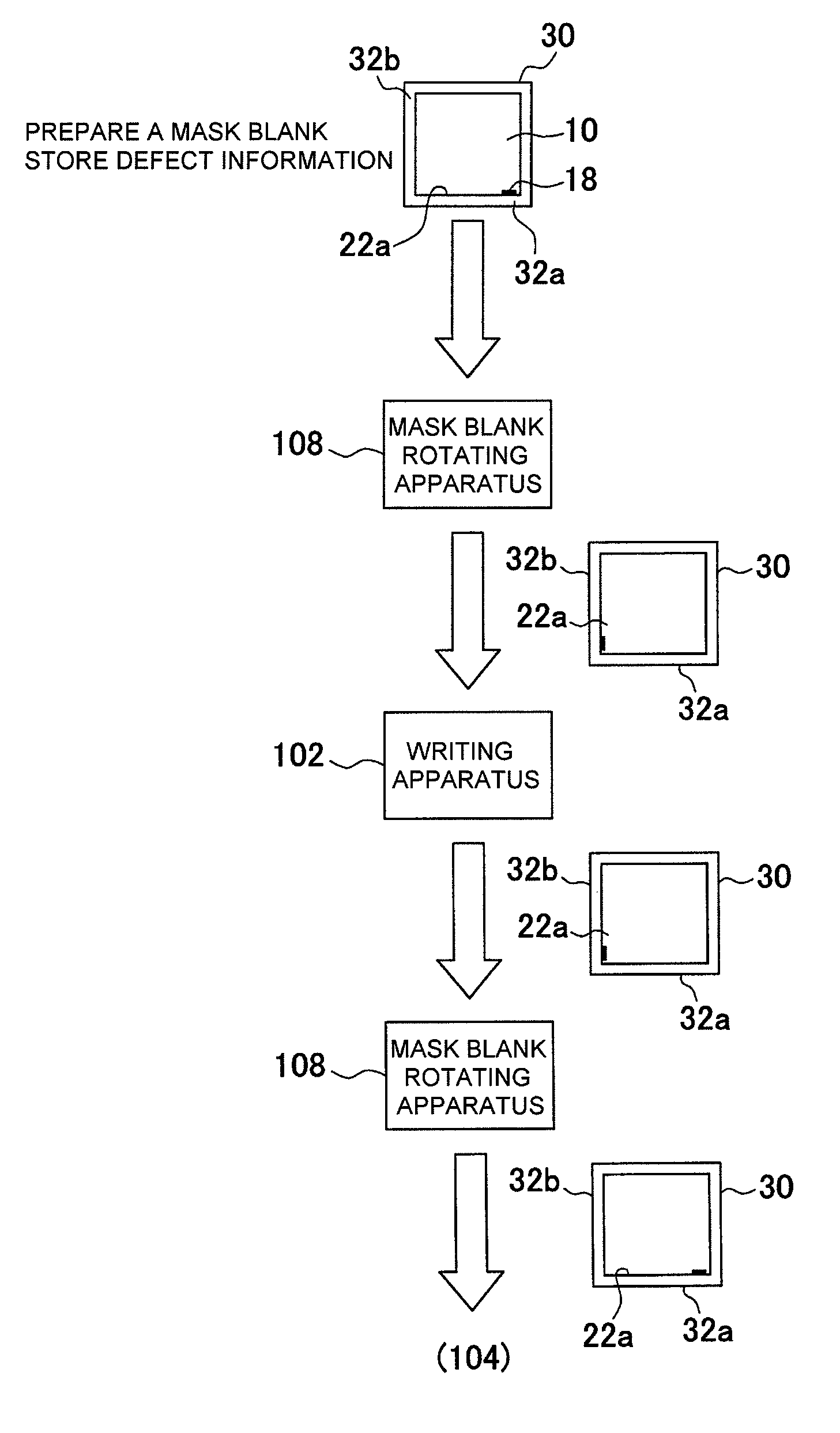
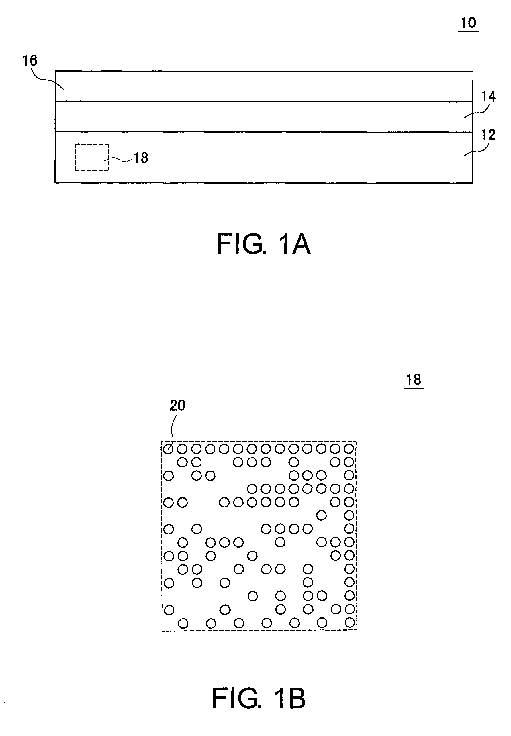
[0049]Hereinbelow, an embodiment according to this invention will be described with reference to the drawings. FIG. 1A shows an example of the structure of a mask blank 10 for use in a photomask manufacturing method according to an embodiment of this invention.

[0050]The mask blank 10 is a mask blank having a mask pattern thin film 14 and a resist film 16 stacked in this order on a substrate 12.

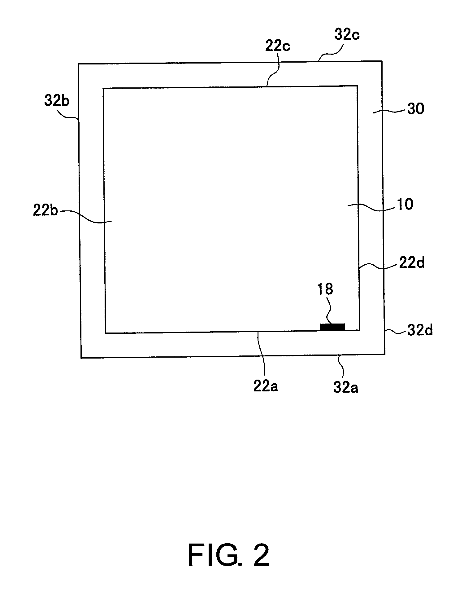
[0051]The substrate 12 is a mask blank glass substrate and is made of, for example, a synthetic quartz glass. The substrate 12 may alternatively be made of a SiO2—TiO2-based low thermal expansion glass, a crystallized glass with a β-quartz solid solution precipitated, a soda-lime glass, or the like. The substrate 12 has main surfaces and end faces each polished to a mirror surface with a predetermined surface roughness. In this example, an identification marker 18 is formed on one of the end faces of the substrate 12. The mask pattern thin film 14 is a light-shielding film, a light-semitransmi...


PUM

PropertyMeasurementUnit
rotation angleaaaaaaaaaa

Abstract

A photomask manufacturing method includes a defect information storage step of storing defect information of a mask blank, provided with an identification marker on an end face thereof, into an information storage device in correspondence to the identification marker, a placing orientation determination step of determining a placing orientation of the mask blank with respect to an exposure / writing apparatus, and an orientation correction step of performing rotation control of a rotating apparatus so that an orientation of the mask blank coincides with the determined placing orientation.

Description

[0001]This application is based upon and claims the benefit of priority from Japanese Patent Application No. 2008-168239, filed on Jun. 27, 2008, the disclosure of which is incorporated herein in its entirety by reference.TECHNICAL FIELD[0002]This invention relates to a photomask manufacturing method.BACKGROUND ART[0003]In advanced manufacturing of masks, there has been employed a technique that feeds back the quality of mask blanks being a material of the masks. For example, a method is known that performs pattern formation while avoiding a defective portion of a mask blank (see, e.g. Japanese Unexamined Patent Application Publication (JP-A) No. 2001-33941 (Patent Document 1)).[0004]In order to perform such feedback, it is necessary to identify individual mask blanks. For this purpose, there have been proposed, for example, a mask blank formed with an identification marker for identifying or managing a mask blank glass substrate and a mask blank provided with an optically readable ...

Claims


Application Information

Patent Timeline
Patent Type & Authority Patents(United States)
IPC IPC(8): G03F1/00G03F9/00G03F1/24G03F1/38H01L21/027
CPCG03F1/42G03F1/14G03F1/62G03F1/70G03F1/72G03F7/70433
Inventor OKUBO, YASUSHIKASAHARA, HISASHI
Owner HOYA CORP
Why Eureka
Try Eureka