Heat processing furnace and vertical-type heat processing apparatus

a heat processing furnace and vertical-type technology, applied in the field of heat processing furnaces and vertical-type heat processing apparatuses, can solve the problems of slow increase in length, heating element likely to be deformed, heating element undergoes creep strain, etc., and achieves rapid increase and decrease of temperature, improve durability, and reduce cost

Active Publication Date: 2011-09-20
TOKYO ELECTRON LTD
View PDF15 Cites 7 Cited by
  • Summary
  • Abstract
  • Description
  • Claims
  • Application Information

AI Technical Summary

Benefits of technology

[0014]The present invention has been made under the above circumstances. The object of the present invention is to provide a heat processing furnace and a vertical-type heat processing apparatus that are capable of quickly increasing and decreasing a temperature, while achieving improvement in durability and reduction in cost.
[0024]The present invention is the heat processing surface, wherein the heat insulating member is provided with a falling-down prevention plate that supports a lower part of the peak portion of the heating resistor so as to prevent falling-down of thereof.
[0034]The present invention is the vertical-type heat processing apparatus, wherein the heat insulating member is provided with a falling-down prevention plate that supports a lower part of the peak portion of the heating resistor so as to prevent falling-down of thereof.
[0035]According to the present invention, the heating resistor, which is manufactured by forming a strip-shaped heating resistor into a waveform, is placed in an exposed manner along the inner circumferential surface of the heat insulating member. Thus, a temperature can be quickly increased and decreased, and improvement in durability and reduction in cost can be achieved.

Problems solved by technology

However, by using the heating element under a high temperature, the heating element undergoes a creep strain, and slowly increases in length over time.
Due to the repeated rise and drop in temperature, the heating element is likely to be deformed.
This may generate a short-circuit between adjacent parts of the deformed heating element, which may invite disconnection.
Thus, there is a possibility that a short-circuit occurs between a part and another part adjacent thereto of the heating element, resulting in some disconnection.
However, in the above structure in which the fixing member is merely joined to the outside portion of the heating element by welding, the joined portion is exposed to a high temperature.
In addition, it can be considered that a stress tends to concentrate on the joined portion when the heating resistor is thermally expanded or thermally shrunk, which entails deterioration in durability (reduction in lifetime) of the heating element.
Further, since the fixing member has a bar-like shape, the fixing member may easily drop out of the heat insulating member, whereby it is difficult to secure a sufficient holding force for the fixing member.
Moreover, when it is desired to quickly increase or decrease the temperature of a wafer, a large power has to be applied to a heating element during the quick temperature-increasing operation.
However, a conventional, general heating element may not withstand the large load, and may be prone to be disconnected.
For this reason, such a large power cannot be actually applied, and thus the quick temperature increase / decrease operation has been limited.
Although the use of a heating element resistant to disconnection can overcome the difficulty, this incurs increase in cost because such a heating element is expensive.
Thus, an object to be heated in a reactor core is heated via the heat insulating member 16, so that it is difficult to quickly increase a temperature of the object.
Thus, durability of the heating element may be not sufficient.
Similarly to the spiral-type heating element, although this type of heating element can have an increased surface area, but has the same disadvantage in terms of installation thereof in a cylindrical insulating member.

Method used


Image

  • Heat processing furnace and vertical-type heat processing apparatus
  • Heat processing furnace and vertical-type heat processing apparatus
  • Heat processing furnace and vertical-type heat processing apparatus

Examples


Embodiment Construction

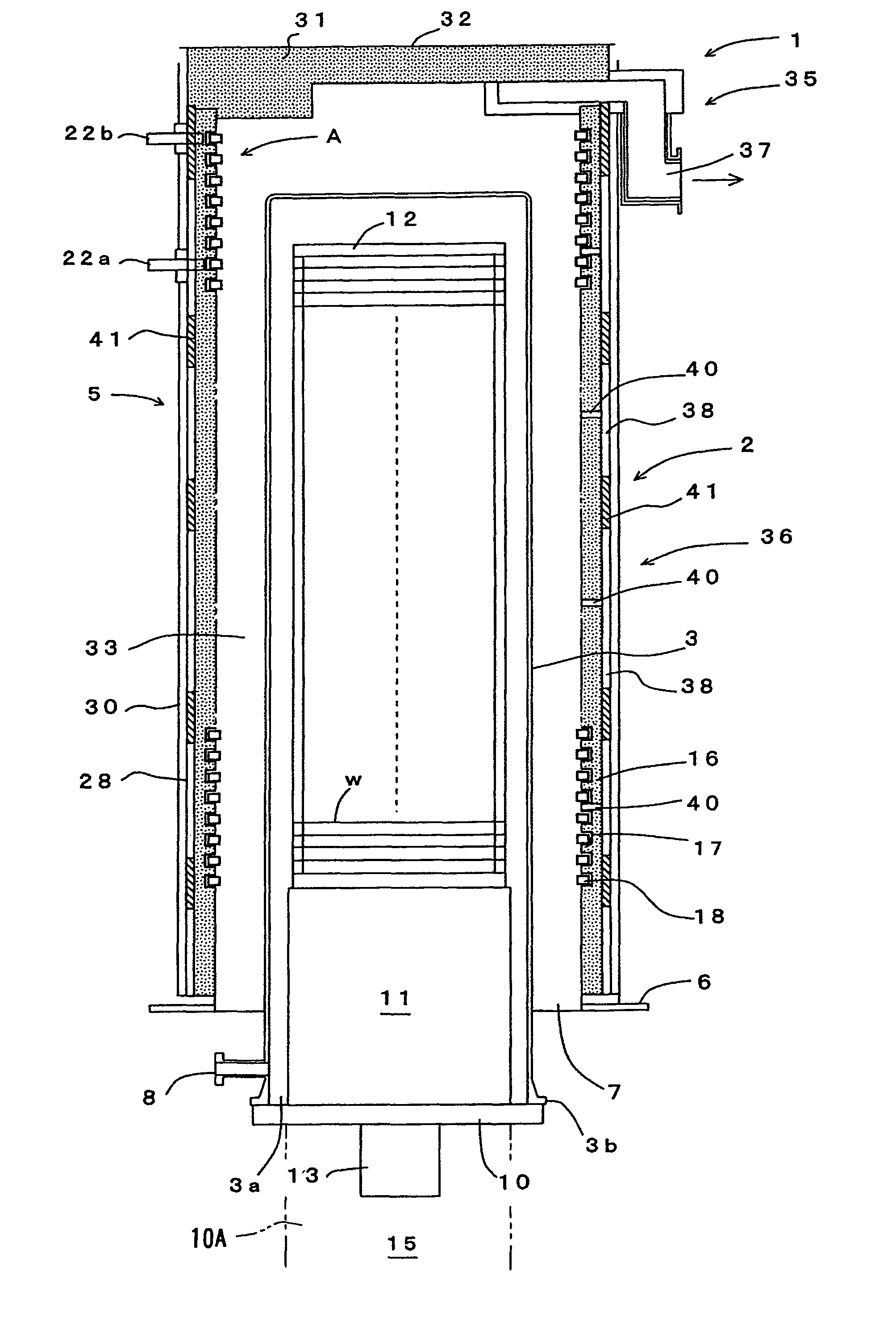
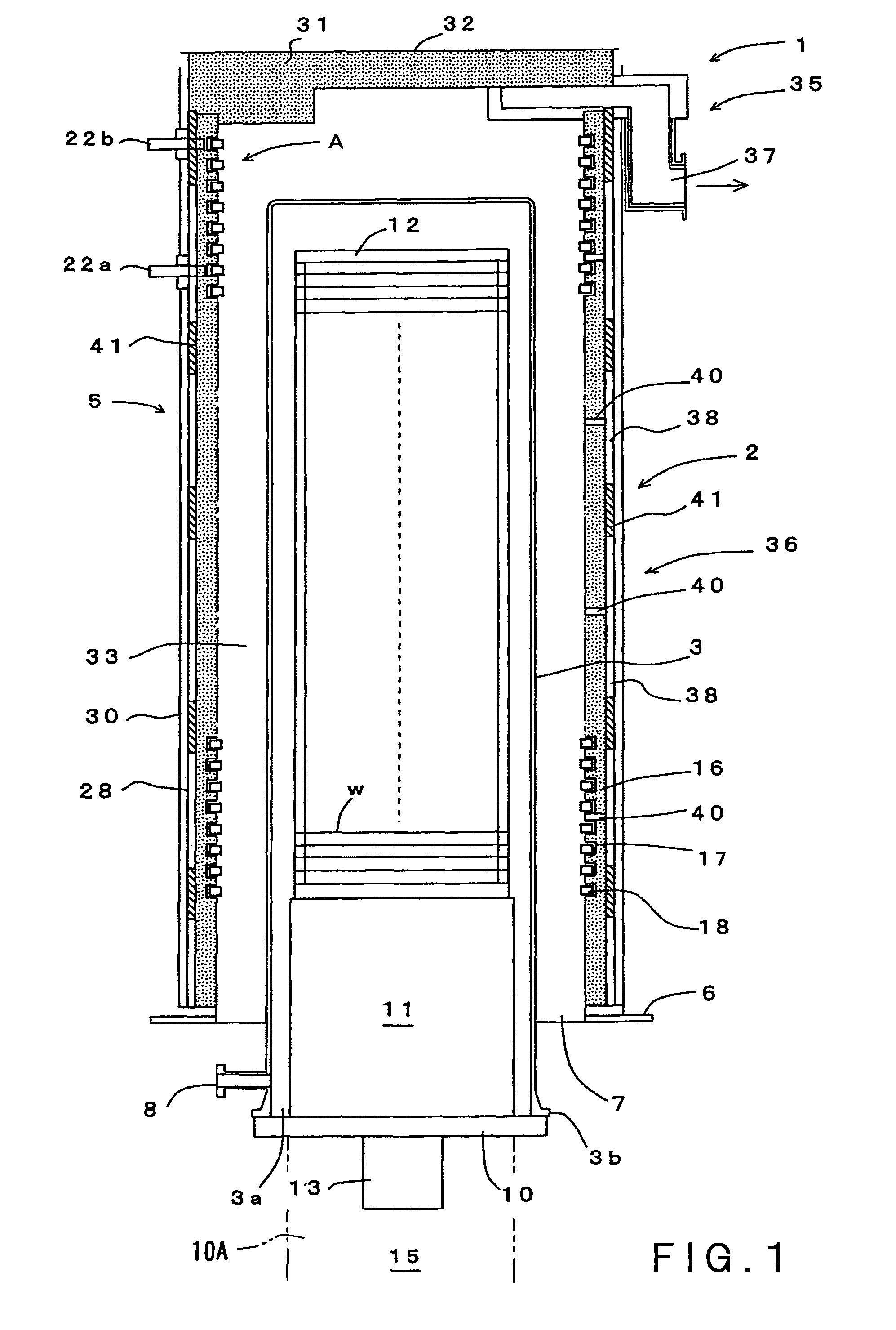
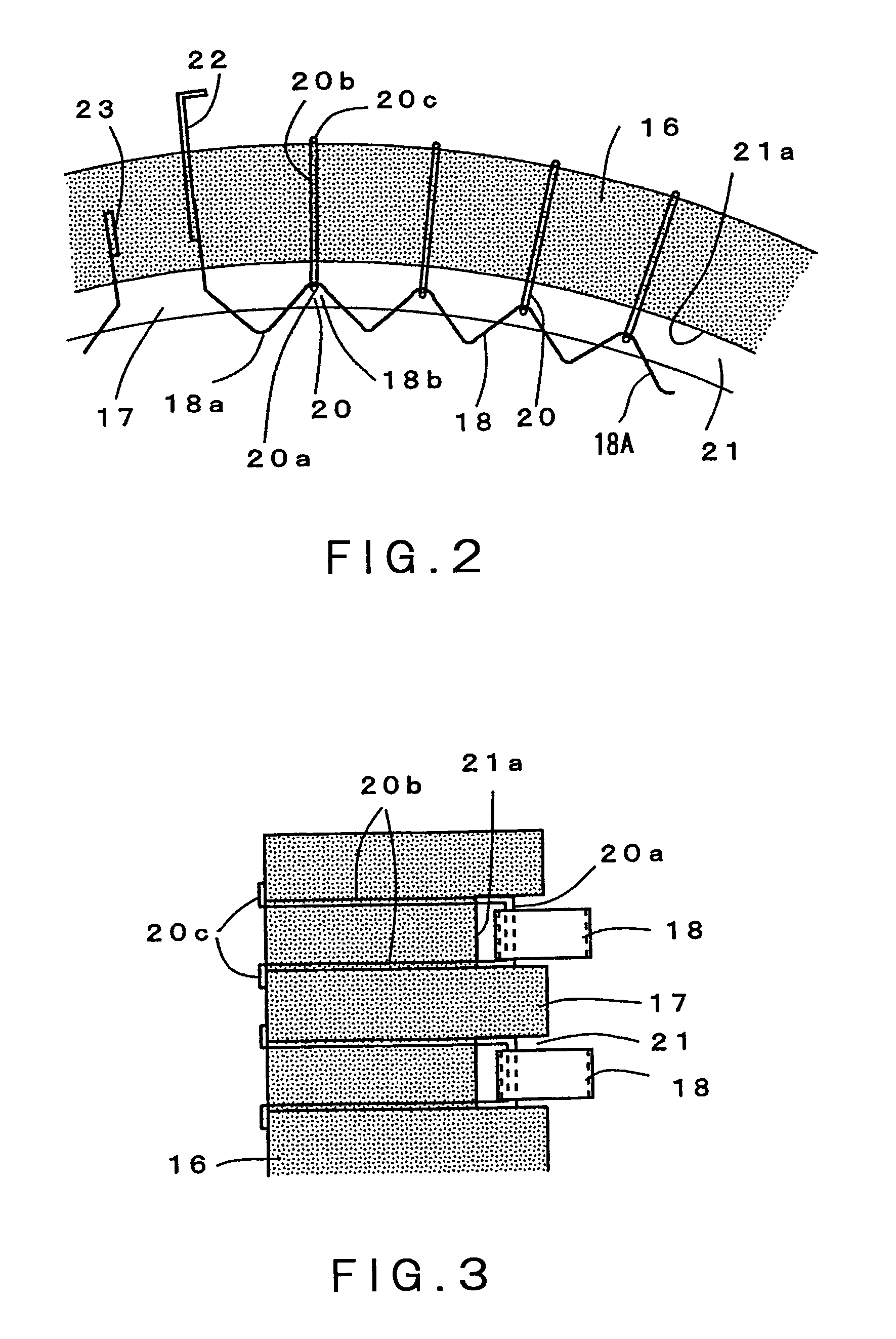
[0050]The best mode for carrying out the present invention will be described in detail with reference to the attached drawings. FIG. 1 is a longitudinal sectional view schematically showing an embodiment of a vertical-type heat processing apparatus of the present invention. FIG. 2 is an enlarged cross-sectional view of a part A in FIG. 1. FIG. 3 is an enlarged longitudinal view of the part A. FIG. 4 is a plan view of a heating element. FIG. 5 is a side view of the heating element.

[0051]FIG. 1 shows a vertical-type heat processing apparatus 1 which is a kind of a semiconductor manufacturing apparatus. The heat processing apparatus 1 includes a vertical-type heat processing furnace 2 that can simultaneously accommodate a number of objects to be processed such as semiconductor wafers w, and can perform thereto a heat process such as an oxidation process, a diffusion process, and a reduced-pressure CVD process. The heat processing furnace 2 includes: a processing vessel (also referred t...


PUM


Abstract

There is provided a heat processing furnace capable of quickly increasing and decreasing a temperature, while achieving improvement in durability. A heat processing furnace 2 comprises: a processing vessel 3 for accommodating an object to be processed w and performing thereto a heat process; and a cylindrical heater 5 disposed to surround an outer circumference of the processing vessel 3, for heating the object to be processed w. The heater 5 includes a cylindrical heat insulating member 16, and heating resistors 18 arranged along an inner circumferential surface of the heat insulating member 16. Each of the heating resistors 18 is formed of a strip-shaped member that is bent into a waveform having peak portions and trough portions. Pin members 20 are arranged in the heat insulating member 16 at suitable intervals therebetween, the pin members 20 holding the heating resistor 18 such that the heating resistor 18 is movable in a radial direction of the heater.

Description

CROSS REFERENCE TO RELATED APPLICATIONS[0001]This application is based upon and claims the benefit of priority from the prior Japanese Patent Application No. 2007-72477 filed on Mar. 20, 2007, and Japanese Patent Application No. 2008-25113 filed on Feb. 5, 2008, the entire contents of which are incorporated herein by reference.TECHNICAL FIELD[0002]The present invention relates to a heat processing furnace and a vertical-type heat processing apparatus including the heat processing furnace.BACKGROUND ART[0003]When a semiconductor device is manufactured, various heat processing apparatuses are used for subjecting a semiconductor wafer, which is an object to be processed, to processes such as an oxidation process, a diffusion process, and a CVD (Chemical Vapor Deposition) process. A general heat processing apparatus includes a heat processing furnace which is composed of: a processing vessel (reaction tube) capable of accommodating semiconductor wafers and heat-processing the same; and ...

Claims


Application Information

Patent Timeline
Patent Type & Authority Patents(United States)
IPC IPC(8): A21B2/00
CPCF26B23/06F27B17/0025H01L21/67109
Inventor ICHIKAWA, TAKASHIKOBAYASHI, MAKOTOYAMAGA, KENICHI
Owner TOKYO ELECTRON LTD
Why Eureka
Try Eureka