Method of liquid droplet formation and transport apparatus therefor and particle manipulating apparatus

a technology of liquid droplet and transport apparatus, which is applied in the direction of liquid dispensing, positive displacement liquid engine, special dispensing means, etc., can solve the problems of difficult to make varying combinations of probe types, time and effort, and high cost, and achieve low manufacturing cost, simple manipulation of transport objects, and high efficiency

Inactive Publication Date: 2011-10-04
HITACHI LTD
View PDF12 Cites 21 Cited by
  • Summary
  • Abstract
  • Description
  • Claims
  • Application Information

AI Technical Summary

Benefits of technology

[0030]The present invention ensures that particles having biomolecules immobilized thereon, one by one, can be introduced into the particle array container and be arrayed therein, thus making it possible to fabricate particle arrays each formed of an array of plural different particles, with high efficiency at low manufacturing cost. Also, the use of the apparatus of the present invention enables the trace dispensing of the liquid sample, thus enabling simple manipulation of transport objects including not only particles but also liquids.

Problems solved by technology

With any of these methods, the fabrication of the chip requires the immobilization of the DNA probes or the protein probes on each array, or the base-by-base synthesis of the oligomers if specialized for the DNA probes; hence the fabrication takes time and effort, resulting in high costs.
Also, the probes are generally mounted as liquid droplets on the surface of the solid body, which in turn involves problems in that there is compartment-to-compartment variation, that it is not easy to make varying combinations of the types of probes, and that manipulation is not easy for a user, and so on.
However, these methods have a problem with reliability or usability because of often taking in the particles unsuccessfully under the influence of air bubbles.

Method used


Image

  • Method of liquid droplet formation and transport apparatus therefor and particle manipulating apparatus
  • Method of liquid droplet formation and transport apparatus therefor and particle manipulating apparatus
  • Method of liquid droplet formation and transport apparatus therefor and particle manipulating apparatus

Examples


first embodiment

[0066]Referring to the first embodiment, description will be given with regard to a liquid droplet formation method and an intermittent fluid transport method of the present invention, based on an experiment in which pure water is used.

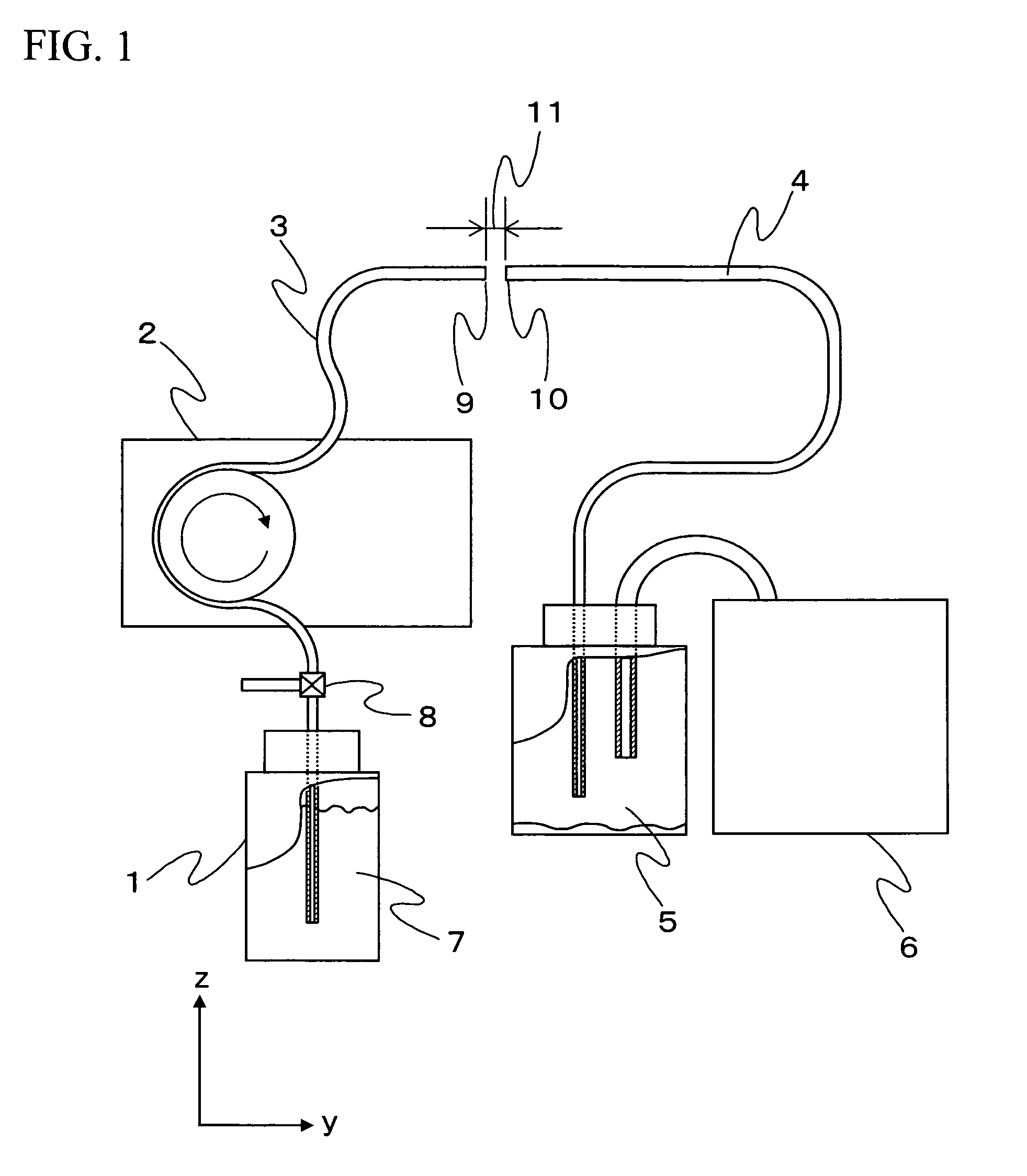
[0067]FIG. 1 is a general schematic view showing an experimental system for the liquid droplet formation method and the intermittent fluid transport method of the present invention. The experimental system includes a liquid container 1, a first liquid feed pump 2, a first liquid transport pipe 3, a second liquid transport pipe 4, a liquid collecting container 5, and a suction pump 6. The liquid container 1 is stocked with pure water 7. Also, a three-way valve 8 is interposed between the liquid container 1 and the first liquid feed pump 2. Here, a peristaltic pump is used as the first liquid feed pump 2; and an aspirator, as the suction pump 6. However, a diaphragm pump may be used in place of the peristaltic pump; or a peristaltic pump, a diaphragm pu...

second embodiment

[0077]Referring to the second embodiment, description will be given with regard to a particle manipulating apparatus and a method therefor. Here covered is a method for fabricating a particle array in the second liquid transport pipe 4. Description will be given with regard to an instance where plural types of particles are prepared by having a fixed particle diameter and immobilizing biological molecular probes on the surfaces of the particles and the particles are arrayed in a line in predefined sequence in the second liquid transport pipe 4, with reference to a view of apparatus configuration and based on the principle of operation.

[0078]FIG. 6 is a schematic view showing an example of the particle manipulating apparatus of the present invention. A particle accommodating plate 20 having plural accommodating units 19 holding particles having immobilized thereon biological probes bonded to biomolecules such as DNA, RNA or protein, and a plate mounting jig 21 are mounted on a first ...

third embodiment

[0096]FIGS. 9 and 10 show two examples of apparatus configuration having a parallel arrangement of particle manipulating means described with reference to FIG. 6 and FIGS. 7(A) to 7(G).

[0097]In FIG. 9, the particle capturing nozzles 25, the number of which is five, are mounted to the particle capturing nozzle mounting jig 26. The particle capturing nozzles 25 are arranged in side by side relation parallel to the x-z plane at given spaced intervals in the direction of the x axis. Also, the openings of the particle capturing nozzles 25 are all in the same position in the direction of the z axis. Also installed are the first liquid transport pipes 3 and the second liquid transport pipes 4, the numbers of which are likewise each five. The first liquid transport pipes 3 and the second liquid transport pipes 4 are arranged in side by side relation parallel to the x-y plane at given spaced intervals in the direction of the x axis. Also, the openings of the first and second liquid transport...


PUM

PropertyMeasurementUnit
volumeaaaaaaaaaa
diametersaaaaaaaaaa
diameteraaaaaaaaaa

Abstract

The present invention provides an apparatus for efficiently transporting or dispensing transport objects including not only particles but also liquid samples. A liquid in a first liquid transport pipe (3) is fed at a liquid feed velocity (V1), and a liquid droplet is formed toward an open end of a second liquid transport pipe (4) disposed with an air gap (11) in between. The particle is released into the liquid droplet, so that the particle is enclosed in the liquid droplet. Suction with a liquid feed velocity (V2) is applied to the inside of the second liquid transport pipe. Since the relationship between V1 and V2 is V1<V2, the liquid droplet, after reaching the open end (10) of the second liquid transport pipe, is sheared off by suction, thereby forming a liquid section in the second liquid transport pipe. Thus, the particle in the liquid section, held under surface tension on a gas-liquid phase boundary, can be transported into a particle array container with stability in conjunction with the liquid section.

Description

TECHNICAL FIELD[0001]The present invention relates to techniques for liquid droplet formation and transport, and techniques for manipulation of transport objects such as particles and trace liquid samples, using liquid droplets.BACKGROUND ART[0002]With the genome project going forward, there has been an active move afoot to grasp a living organism at the DNA or protein level for examination for disease or understanding of the phenomena of life. To examine the status of gene expression is effective for the understanding of the phenomena of life or the investigation of the workings of genes. A probe array, namely, a DNA chip or a protein chip, having many DNA probes or protein probes partitioned according to the type of probe and immobilized on the surface of a solid body such as slide glass, has come into use as an effective method for examination of the status of gene expression. Chip making methods include a method that involves synthesizing a designed sequence of oligomers, base b...

Claims


Application Information

Patent Timeline
Patent Type & Authority Patents(United States)
IPC IPC(8): B01L3/00G01N11/00G01N21/00G01N13/00B67D7/08
CPCB01J19/0046B01L3/0241G01N35/1016B01F13/0071B01J2219/00315B01J2219/00369B01J2219/00376B01J2219/00468B01J2219/005B01J2219/00648B01L3/0289B01L2200/0605B01L2200/0647B01L2200/0673B01L2300/0838B01L2400/0487G01N2035/00574G01N2035/1046B01F33/3021
Inventor NODA, HIDEYUKIKOHARA, YOSHINOBUUCHIDA, KENKO
Owner HITACHI LTD
Why Eureka
Try Eureka