Hybrid working vehicle
a hybrid working and vehicle technology, applied in the direction of jet propulsion mounting, fluid couplings, lighting and heating apparatus, etc., can solve the problems of difficult reduction of manufacturing costs and increase in manufacturing costs of hybrid working vehicles, and achieve the reduction of electric power loss in connected wiring, shortening storage time, and reducing power loss
- Summary
- Abstract
- Description
- Claims
- Application Information
AI Technical Summary
Benefits of technology
Problems solved by technology
Method used
Image
Examples
first exemplary embodiment
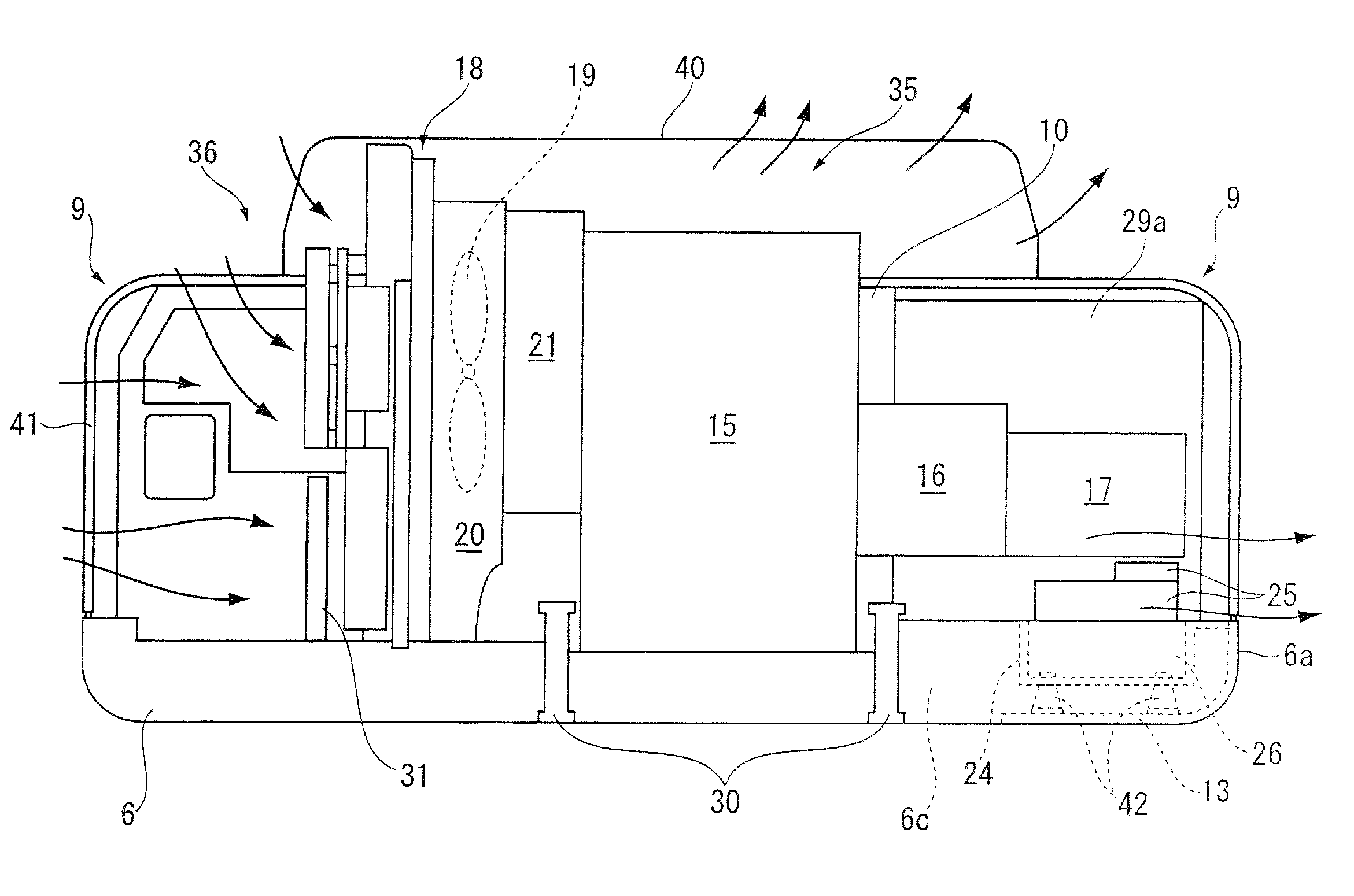
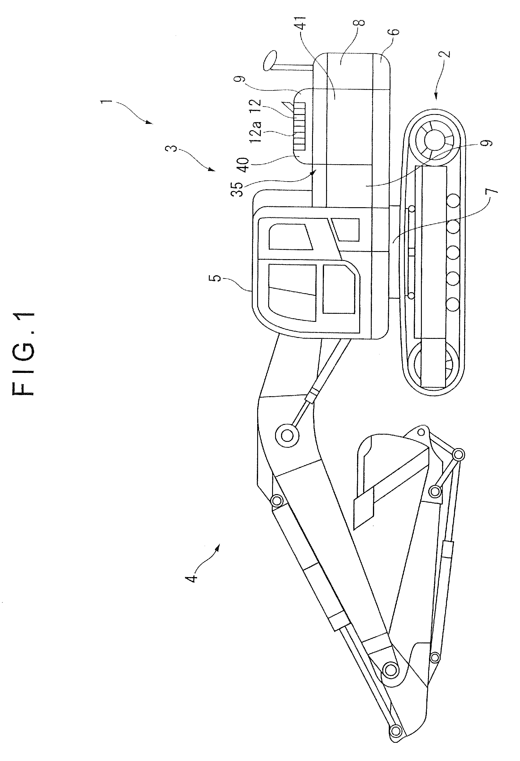
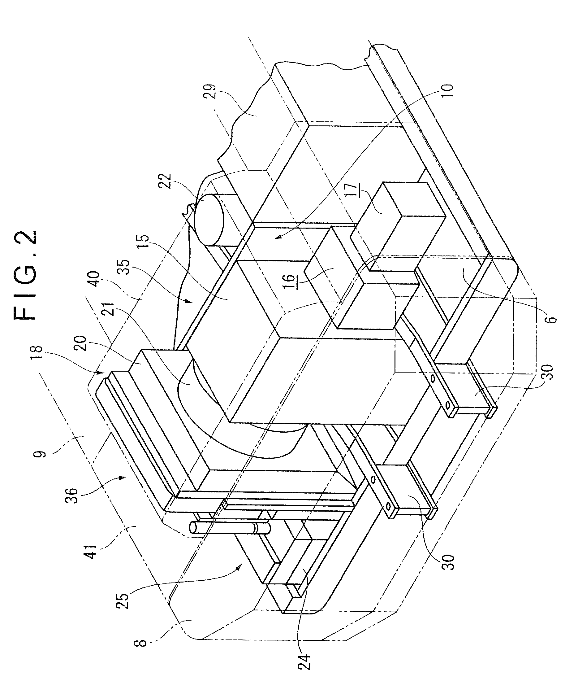
[0052]The hybrid working vehicle according to an exemplary embodiment of the invention will be described below by exemplifying a hybrid hydraulic excavator with reference to FIG. 1. A hydraulic excavator 1 includes an swingable upper swing body 3 mounted on an upper portion of a lower traveling body 2 through a swing circle 7. The upper swing body 3 is swingably provided by a later-described swing motor 22 (see FIGS. 2 and 3).
[0053]An upper swing body frame 6 is provided on a bottom portion of the upper swing body 3. An outer cover 9 covering an engine room 35, a counterweight 8 forming the engine room 35 with the outer cover 9, an operation room 5, a working machine 4 and the like are mounted on the upper swing body frame 6. The outer cover 9 is directly attachable to a later-described outer frame 11 (see FIG. 5) through a bolt or the like.
[0054]An engine hood 40 is provided in a portion covering the engine room 35 as a part of the outer cover 9. A door 41 is openably and closably ...
second exemplary embodiment
[0085]FIG. 8 is a schematic rear view illustrating an engine room showing another exemplary embodiment according to the invention. According to the first exemplary embodiment, the electronic unit 38 is disposed in the intake chamber 36. However, the electronic unit 38 is disposed close to the main hydraulic pump 17 of the power unit according to the second exemplary embodiment. Other components according to the exemplary embodiment are arranged in the same manner as in the first exemplary embodiment. In the following embodiment, the same components as in the exemplary embodiment 1 are denoted by the same reference numerals, and thus detailed description thereof will be hereinafter omitted.
[0086]As shown in FIG. 8, the cooling heat sink 24 in which the electronic unit 38 is disposed is arranged on the under cover 13 (see FIG. 6) formed within the side frame 6a of the upper swing body frame 6 in a space under the main hydraulic pump 17. Like the first exemplary embodiment, the electro...
third exemplary embodiment
[0090]FIG. 9 is a schematic rear view illustrating an engine room showing still another exemplary embodiment according to the invention. In the third exemplary embodiment, the cooling fan 19 driven by the engine 15 is disposed in the wind tunnel 21 such that a part of the cooling fan 19 (approximately ⅓ of the cooling fan 19) is exposed in a space close to the engine 15. According to such an arrangement, cooling air can be effectively sucked and cooling efficiency in the cooling components can be enhanced.
[0091]According to such an arrangement, except for that the storage 26, the controller 25, the cooling pump 27 and the radiator 31 for the controller are arranged in the intake chamber 36, and the swing motor 22 is provided as a swing motor of the upper swing body, a conventional arrangement of the hydraulic excavator can be commonly used. Consequently, a manufacturing cost increase of a hybrid hydraulic excavator can be limited.
PUM
 Abstract
Description
Claims
Application Information
 - R&D
- Intellectual Property
- Life Sciences
- Materials
- Tech Scout
- Unparalleled Data Quality
- Higher Quality Content
- 60% Fewer Hallucinations
Browse by: Latest US Patents, China's latest patents, Technical Efficacy Thesaurus, Application Domain, Technology Topic, Popular Technical Reports.
© 2025 PatSnap. All rights reserved.Legal|Privacy policy|Modern Slavery Act Transparency Statement|Sitemap|About US| Contact US: help@patsnap.com


