Hybrid working vehicle

a hybrid working and working vehicle technology, applied in the direction of fluid couplings, lighting and heating apparatus, couplings, etc., can solve the problems of difficult reduction of manufacturing costs and increased manufacturing costs of hybrid working vehicles, and achieve the reduction of electric power loss in connected wiring, shortening storage time, and reducing power loss

Active Publication Date: 2009-08-13
KOMATSU LTD
View PDF9 Cites 51 Cited by
  • Summary
  • Abstract
  • Description
  • Claims
  • Application Information

AI Technical Summary

Benefits of technology

[0023]According to the aspect of the invention, since the storage for storing electric power generated by the generator-motor is provided on at least one of the side close to the engine of the power unit and the side close to the main hydraulic pump of the power unit, a connected wiring between the generator-motor and the storage can be shortened. Thus, electric power loss in the connected wiring can be reduced. Further, since the hybrid working vehicle can be operated with a reduced power loss, the working efficiency of the hybrid working vehicle can be improved.
[0024]When the storage is provided on the side close to the engine of the power unit, the storage can be provided close to an air flow caused by suction of a cooling fan for cooling a radiator and the like. Thus, the storage can be effectively cooled by using the air flow. Further, since the storage can be provided in a place where the air flow that is delivered into the radiator and the like is only slightly disturbed, the cooling efficiency of the radiator and the like is not lowered.

Problems solved by technology

Mounting positions of such devices cause a problem.
However, as compared with a conventional working vehicle, a manufacturing cost of the hybrid working vehicle has been increased in order to arrange a generator-motor, a motor, a controller therefor, a cooling circuit therefor and the like.
Further, when a new design suitable to the hybrid working vehicle is made, a conventional frame structure and the like for the conventional working vehicle cannot be used, which makes it difficult to reduce the manufacturing cost.

Method used


Image

  • Hybrid working vehicle
  • Hybrid working vehicle
  • Hybrid working vehicle

Examples


first exemplary embodiment

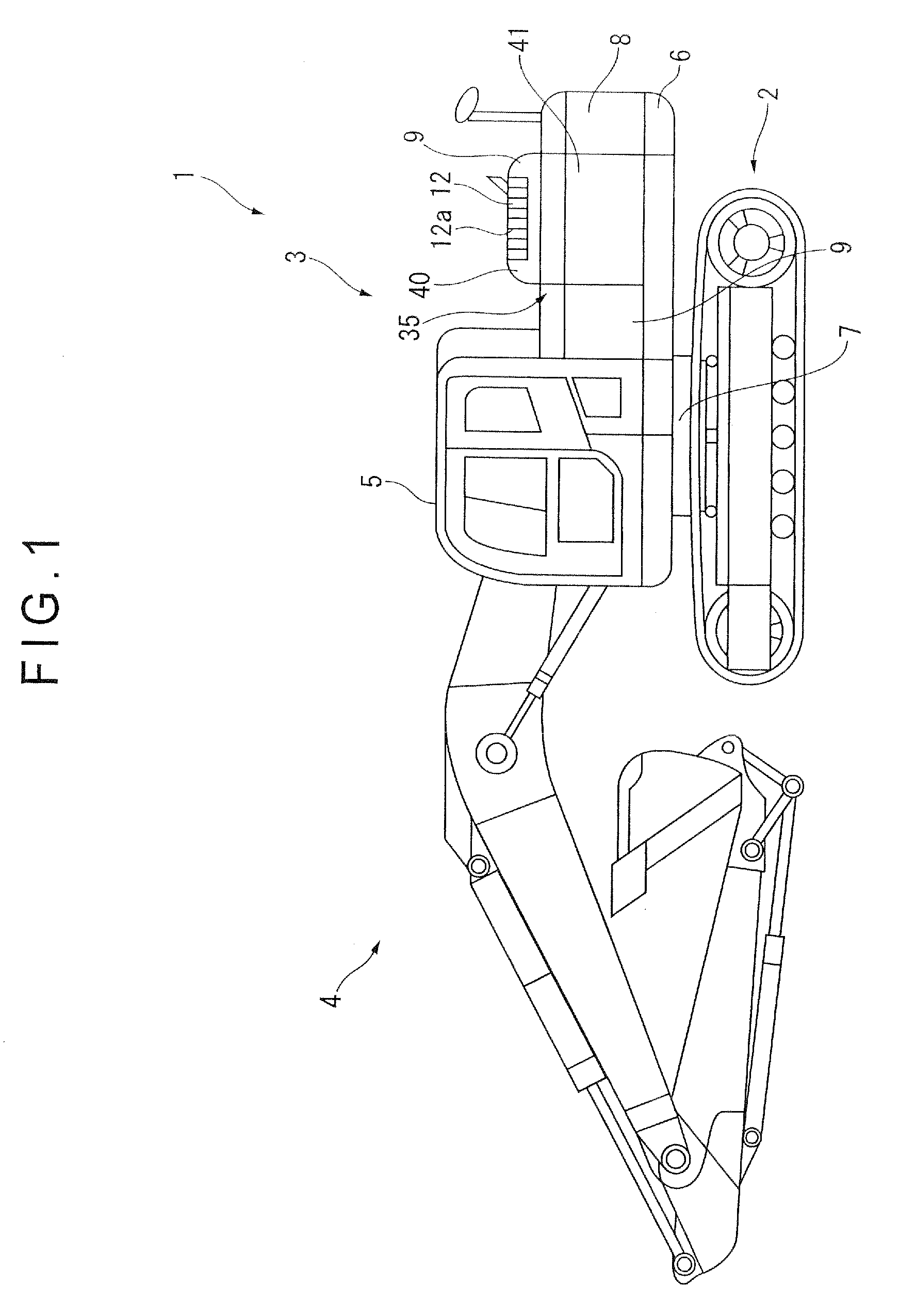
[0052]The hybrid working vehicle according to an exemplary embodiment of the invention will be described below by exemplifying a hybrid hydraulic excavator with reference to FIG. 1. A hydraulic excavator 1 includes an swingable upper swing body 3 mounted on an upper portion of a lower traveling body 2 through a swing circle 7. The upper swing body 3 is swingably provided by a later-described swing motor 22 (see FIGS. 2 and 3).

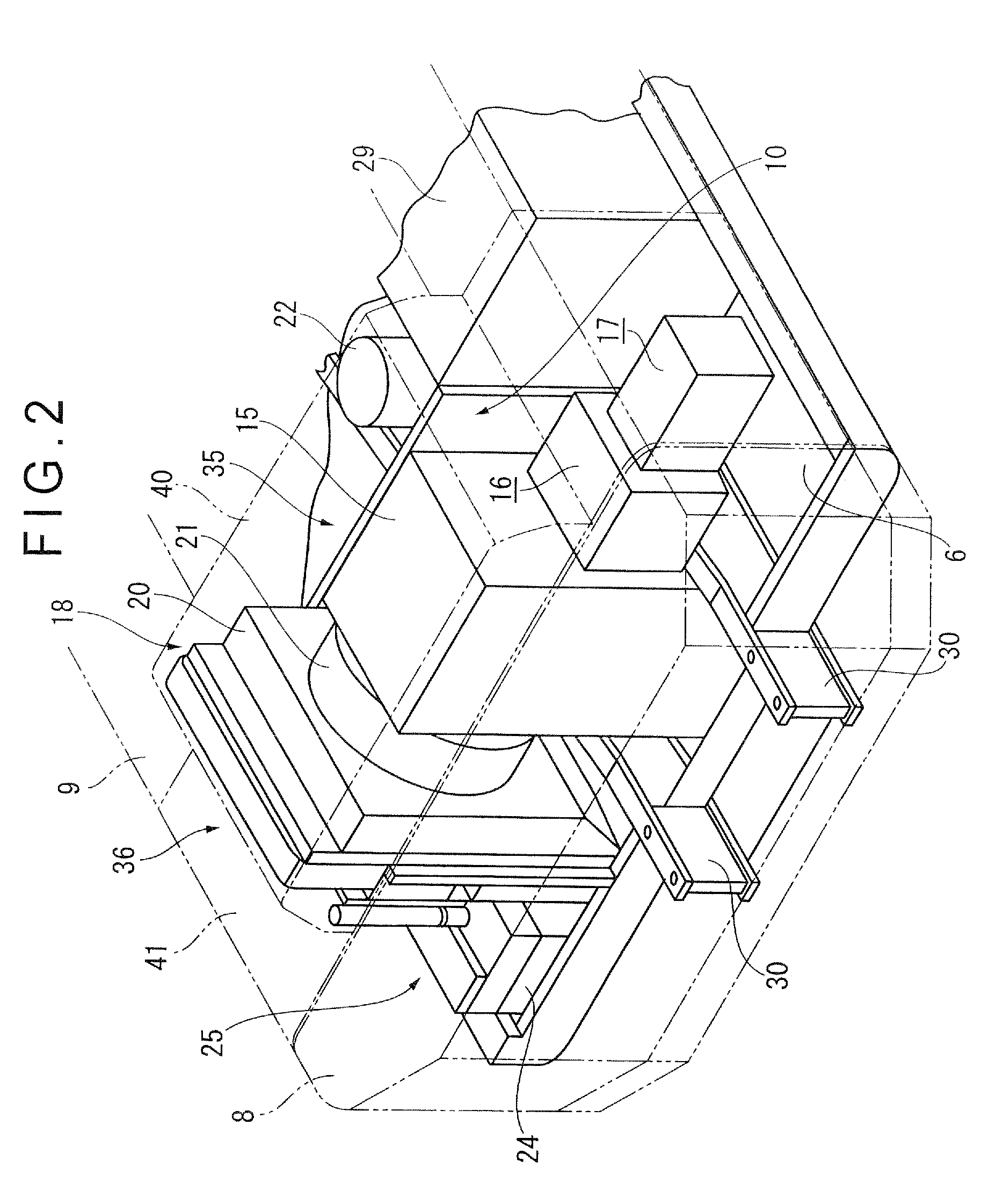
[0053]An upper swing body frame 6 is provided on a bottom portion of the upper swing body 3. An outer cover 9 covering an engine room 35, a counterweight 8 forming the engine room 35 with the outer cover 9, an operation room 5, a working machine 4 and the like are mounted on the upper swing body frame 6. The outer cover 9 is directly attachable to a later-described outer frame 11 (see FIG. 5) through a bolt or the like.

[0054]An engine hood 40 is provided in a portion covering the engine room 35 as a part of the outer cover 9. A door 41 is openably and closably ...

second exemplary embodiment

[0085]FIG. 8 is a schematic rear view illustrating an engine room showing another exemplary embodiment according to the invention. According to the first exemplary embodiment, the electronic unit 38 is disposed in the intake chamber 36. However, the electronic unit 38 is disposed close to the main hydraulic pump 17 of the power unit according to the second exemplary embodiment. Other components according to the exemplary embodiment are arranged in the same manner as in the first exemplary embodiment. In the following embodiment, the same components as in the exemplary embodiment 1 are denoted by the same reference numerals, and thus detailed description thereof will be hereinafter omitted.

[0086]As shown in FIG. 8, the cooling heat sink 24 in which the electronic unit 38 is disposed is arranged on the under cover 13 (see FIG. 6) formed within the side frame 6a of the upper swing body frame 6 in a space under the main hydraulic pump 17. Like the first exemplary embodiment, the electro...

third exemplary embodiment

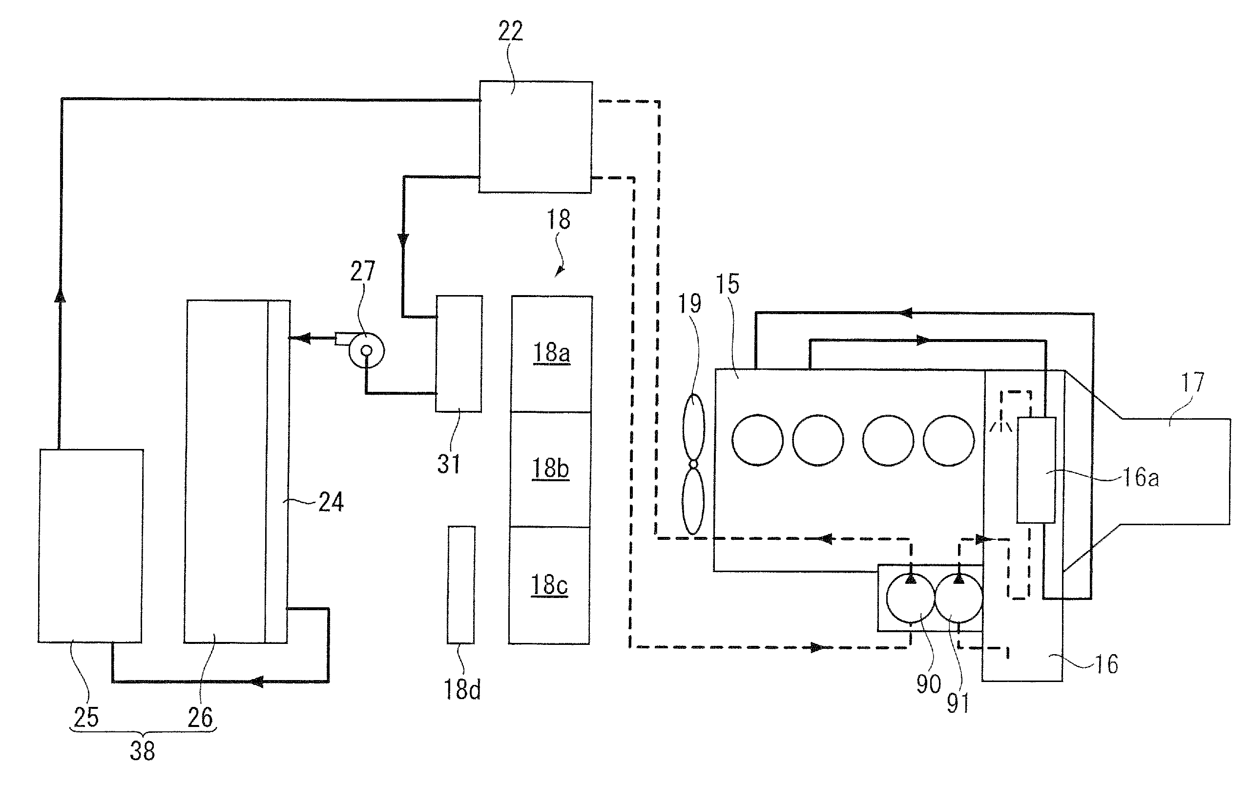
[0090]FIG. 9 is a schematic rear view illustrating an engine room showing still another exemplary embodiment according to the invention. In the third exemplary embodiment, the cooling fan 19 driven by the engine 15 is disposed in the wind tunnel 21 such that a part of the cooling fan 19 (approximately ⅓ of the cooling fan 19) is exposed in a space close to the engine 15. According to such an arrangement, cooling air can be effectively sucked and cooling efficiency in the cooling components can be enhanced.

[0091]According to such an arrangement, except for that the storage 26, the controller 25, the cooling pump 27 and the radiator 31 for the controller are arranged in the intake chamber 36, and the swing motor 22 is provided as a swing motor of the upper swing body, an conventional arrangement of the hydraulic excavator can be commonly used. Consequently, a manufacturing cost increase of a hybrid hydraulic excavator can be limited.


PUM


Abstract

An engine room is divided into a left room and a right room by a cooling unit. An intake chamber is disposed at a left side and an engine and the like are disposed at a right side. A cooling heat sink is provided on a side of the intake chamber, and a storage and a controller for controlling hybrid electronic devices are formed in this order in a cooling heat sink. Further, a cooling pump for supplying cooling liquid to the cooling heat sink is provided in the intake chamber. A radiator for cooling the cooling liquid is provided in front of the cooling unit.

Description

TECHNICAL FIELD[0001]The present invention relates to a hybrid working vehicle, and particularly to a hybrid working vehicle having a distinguishing arrangement structure of components for a hybrid system.BACKGROUND ART[0002]In recent years, a hybrid working vehicle employing both an engine and a generator-motor (also called as a motor-generator) has been used as a working vehicle such as a construction machine, a civil engineering machine, an agricultural machine, a delivery vehicle, or a traveling vehicle. In many cases, a hybrid working vehicle has an arrangement in which an engine is transversely disposed in a rear portion of an upper surface of a swinging frame.[0003]For such hybrid working vehicle in which an engine is transversely disposed, an arrangement structure of devices for a construction machine in which storage-related devices are provided in front of a swinging frame has been suggested (see Patent Document 1). Also, a hybrid construction machine having an arrangement...

Claims


Application Information

Patent Timeline
Patent Type & Authority Applications(United States)
IPC IPC(8): F16D31/02F28D15/00H02K9/19
CPCB60K6/20E02F9/2292E02F9/0866B60K2001/003E02F9/2075
Inventor NISHIMURA, SATORUHIRAKI, HIKOSABUROU
Owner KOMATSU LTD
Why Eureka
Try Eureka