
Methods and devices for rhinoplasty and treating internal valve stenosis

a technology of internal valve and stenosis, which is applied in the field of rhinoplasty and treating internal valve stenosis, can solve the problems of affecting the rhinoplasty effect, so as to improve the cross-sectional area of the nose, and improve the rhinoplasty

Active Publication Date: 2011-10-18
KONINKLIJKE PHILIPS ELECTRONICS NV
View PDF15 Cites 12 Cited by
  • Summary
  • Abstract
  • Description
  • Claims
  • Application Information

AI Technical Summary

Benefits of technology

The patent describes a system for supporting a nasal valve using two elongate implants that are connected together. The implants can be connected using complementary socket joints or an eyelet and tether. The system can be used to treat nasal valve disorders by supporting the nasal valve and restoring its proper function. The system can also be used to suspend the nasal valve for therapeutic purposes. The method involves inserting the implants into the nasal passage and securing them to the walls of the nasal passage using tissue anchors and a tether. The system can be delivered using a delivery cannula and the method can include steps of creating an incision and passing the delivery cannula through the incision. The technical effects of the patent are a more effective and reliable system for supporting and suspending a nasal valve.

Problems solved by technology

Another cause can be an extremely wide columella.
The second cause is collapse secondary to rhinologic surgery, especially after removal of the nasal roof.
Deviations of the caudal septum are the most common cause of valvular collapse.
Thickened cartilage can compromise an adequate aperture.
Overresection during rhinoplasty can weaken the cartilage and cause inspiratory collapse.
The tissue can also be too thick, reducing the lumen of the valve.
Although uncommon, some patients may have deformities of the pyriform aperture that reduce the space of the nasal valve.
A more common cause of obstruction is the osteotomy made during a rhinoplasty.
Rhinoplastic procedures are particularly prone to disturbing the nasal valve area.
If the mucosa in the valve is not protected during the surgery, which occurred with the use of many older techniques, scarring of the valve can lead to structure formation or stenosis of the valve.
If the nasal valve is not properly repaired during the surgery, patients may report nasal obstruction after the surgery, even if this was not reported preoperatively.
Overresection of the lower lateral cartilage can lead to pinching and inspiratory collapse.
The result is an increase in nasal resistance to airflow; consequently, the patient reports nasal obstruction.
In this case, the nasal valve is excessively open.
Diagnosis can be difficult if the physician does not visualize the valvular area.
When this returning is excessive, it can produce valve collapse.
In addition to the typical reasons to avoid surgery (e.g., bleeding disorders), other contraindications include excessive scarring due to multiple previous surgeries, which may compromise the outcome of the procedure, the presence of cheloid scarring, and unrealistic patient expectations.
However, these studies are expensive and should not be considered a substitute for comprehensive physical examinations.
Rhinomanometry aids in evaluating the airflow resistance offered by each cavity but does not provide information about the location of the obstruction.
In many male patients (and some females), the vibrissae are thick, making direct visualization of the area difficult.
Some patients use a self-adhesive stent that opens the nasal valve; however, this is only a temporary solution.
The area of transition from skin to respiratory epithelium is prone to developing unwanted scarring or synechiae.
Resection of the caudal border of the ULC reduces its flexibility.
A dry field is important in this surgery because the space is limited and bleeding can obstruct the visual field and make the procedure time consuming.
Septoplasty is a difficult surgery because caudal deviations are commonly complex deformities of the septal framework and obtaining a completely straight septum proves to be a frustrating task.
The nasal roof can be excessively narrowed after rhinoplasty or with congenital or traumatic deformities.
Although complete resection of the turbinate is best avoided, conservative resection (or manicuring) of the head of the turbinate significantly decreases the total resistance offered by the internal valve.
This situation is difficult to handle.
Thus, there remains an unmet need in the art for non-traumatic, non-surgical treatments for the collapse of structures within the nose that form the passageways for airflow.

Method used


Image

  • Methods and devices for rhinoplasty and treating internal valve stenosis
  • Methods and devices for rhinoplasty and treating internal valve stenosis
  • Methods and devices for rhinoplasty and treating internal valve stenosis

Examples


Embodiment Construction

Nasal Suspension

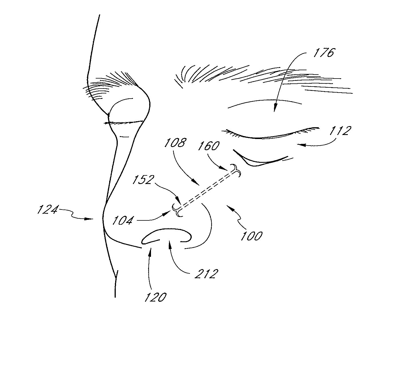
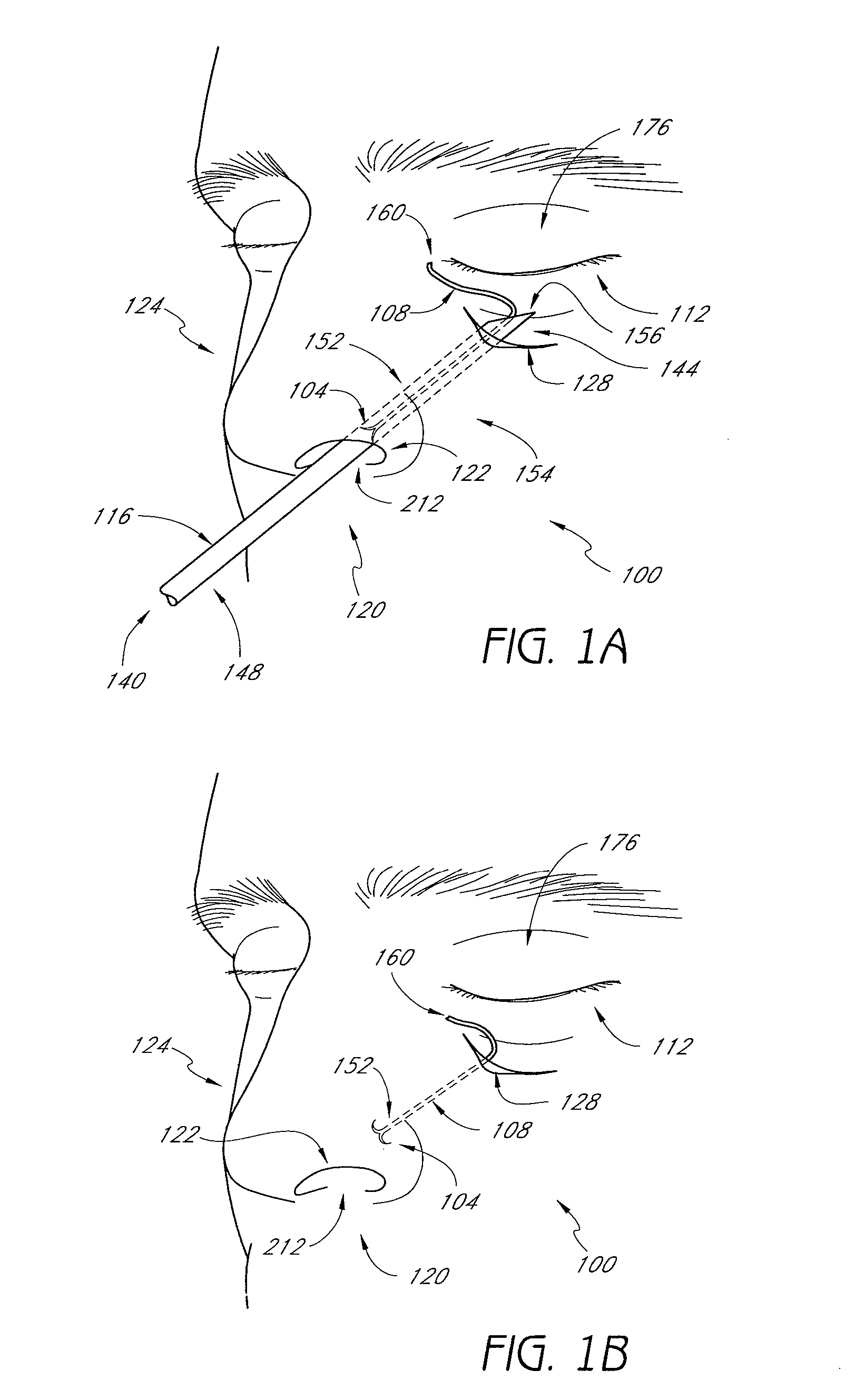
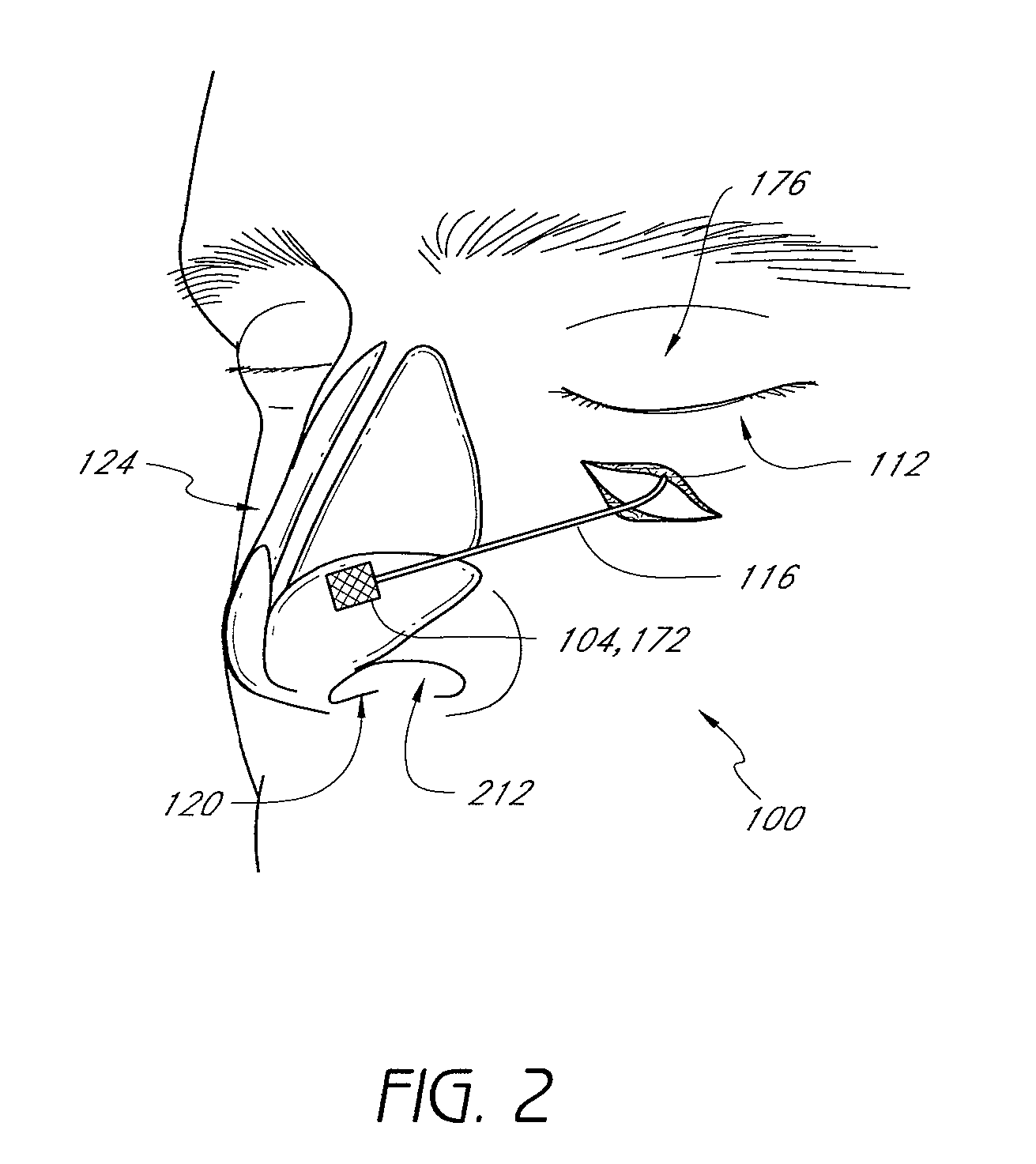
[0088]U.S. patent application, Ser. No. 11 / 349,067, filed Feb. 7, 2006, published as U.S. Patent Publication No. 2006 / 0207608 A1 on Sep. 21, 2006 and incorporated by reference in its entirety, describes methods and devices for manipulating the airway, as does U.S. Patent Publication No. 2006 / 0276817 to Vassallo et al., hereby incorporated by reference in its entirety, an article by David Nunez-Fernandez, M.D. et al., Rhinoplasty, Internal Valve Stenosis, available at www.emedicine.com / ent / topic115.htm, and an article by Michael Friedman, M.D. et al., Nasal Valve Suspension: An Improved, Simplified Technique for Nasal Valve Collapse, January 2003, available at www.chicagoent.com / pdf / Nasal_Valve_Simp1.pdf. Both of the articles are hereby incorporated by reference in their entirety. In some embodiments of the present invention, collapse of structures within the nose that form the passageways for airflow is treated by deploying a nasal suspension assembly 100 within the ...


PUM


Abstract

Methods and devices for rhinoplasty and treating nasal valve stenosis are disclosed herein. The nasal valve acts as a flow-limiter and can contribute to airway obstruction if resistance within the nasal valve is excessive. In one embodiment, a system for treating nasal valve stenosis includes a first elongate implant and a second elongate implant configured to support the nasal valves when implanted. The implants can be coupled together by connecting elements, such as eyelets, tethers, complementary socket joints, and button-rivet supports.

Description

REFERENCE TO RELATED APPLICATIONS[0001]This application claims priority under 35 U.S.C. §119(e) to U.S. Provisional Application No. 60 / 817,565 filed Jun. 29, 2006 and No. 60 / 875,067 filed Dec. 15, 2006. Both of the priority applications are hereby incorporated by reference in their entirety.BACKGROUND OF THE INVENTION[0002]1. Field of the Invention[0003]Embodiments of the present invention disclose devices and methods for treating the collapse of structures within the nose that form the passageways for airflow during inhalation.[0004]2. Description of the Related Art[0005]The airflow resistance provided by the airways during breathing is essential for good pulmonary function. The nose is responsible for almost two thirds of this resistance. Most of this resistance occurs in the anterior part of the nose. This region is called the nasal valve, and it acts as a flow-limiter.[0006]The nasal valve was originally described by Mink in 1903. It is divided into external and internal portion...

Claims


Application Information

Patent Timeline
Patent Type & Authority Patents(United States)
IPC IPC(8): A61F2/18A61M29/00
CPCA61B17/0401A61B17/0469A61F2/186A61F5/08A61B17/24A61B2017/00792A61F2002/2885A61B2017/06176A61B2017/06052
Inventor VAN DER BURG, ERIKDINEEN, MICHAELHIROTSUKA, MARKJACKSON, JASPERFRAZIER, ANDREWROUE, CHAD
Owner KONINKLIJKE PHILIPS ELECTRONICS NV
Learn More