Vapor-liquid contacting apparatuses with vortex contacting stages

a technology of vortex contact and vapor liquid, which is applied in the direction of vapor condensation, combustion air/fuel air treatment, separation processes, etc., can solve the problems and reducing the scope of commercial applications. , to achieve the effect of reducing the potential scope of commercial applications, increasing liquid flow, and reducing the efficiency of stage efficiency

Inactive Publication Date: 2011-11-01
UOP LLC
View PDF12 Cites 9 Cited by
  • Summary
  • Abstract
  • Description
  • Claims
  • Application Information

AI Technical Summary

Benefits of technology

[0010]Embodiments of the invention are therefore directed to vapor-liquid contacting apparatuses, for example reactors and distillation columns (as well as reactive distillation apparatuses), comprising a vessel with one or more vortex contacting stages. The one or more stages provide high interfacial area for the effective contacting of the different phases, in addition to the effective disengagement of these phases after contacting, such that vapor and liquid (with different final compositions relative to their initial compositions) are removed from the stage(s) with reduced entrainment of liquid and vapor, respectively, in the removed phases. The stages additionally avoid limitations of known devices operating in the vortex bubbling regime, and particularly with respect to the operable range of vapor: liquid flow ratios and maximum vapor and / or liquid flows. The vortex contacting stages and associated devices advantageously have a low pressure drop compared to those used conventional vapor-liquid contacting. Additionally, when used in reactors, distillation columns, or other vapor-liquid contacting apparatuses, the devices provide high mechanical integrity, reasonable cost, and ease of installation and inspection.
[0014]In a specific embodiment, which helps maintain stable vortex formation during operation, improves liquid handling capacity, simplifies construction, and reduces cost, the curved outer surface defining a portion of the flow path of liquid exiting the contacting zone terminates at a plurality of liquid downcorner segments extending in discreet sections of an annular space external to and normally surrounding the plurality of vortex contacting stages. Advantageously, the liquid downcorner segments may be disposed radially between other liquid downcorner segments of immediately inferior and / or immediately inferior vortex contacting stages. To further improve the mechanical integrity and reduce stresses on the multi-stage apparatuses described herein, the tangential flow directing devices of successive contacting stages may be arranged to swirl inlet vapors in alternating, clockwise / counterclockwise directions, so that the vortex spin direction is reversed in an alternating manner.

Problems solved by technology

These disadvantages include practical limitations on the range of vapor : liquid flow ratios that can be handled, which reduce the potential scope for commercial applications.
Also, while conventional devices adequately separate liquid from vapor by the centrifugal action of the vortex (i.e., liquid droplets are not substantially entrained in the vapor flow leaving the device), the separation of vapor bubbles from the liquid remains problematic because the vapor flow passes through the liquid phase without the benefit of a disengagement zone for forming a degassed liquid.
When used in fractional distillation, for example, the entrainment of vapor in the liquid flow reduces the stage efficiency (e.g., based on the height equivalent to a theoretical plate, HETP), or may even cause the contacting device or overall apparatus to flood, rendering it inoperable.
The tendency for vapor entrainment increases with increasing liquid flow, and therefore high vapor entrainment can result in practical limits on the overall capacity of the vapor-liquid contacting device and apparatus utilizing the device.

Method used


Image

  • Vapor-liquid contacting apparatuses with vortex contacting stages
  • Vapor-liquid contacting apparatuses with vortex contacting stages
  • Vapor-liquid contacting apparatuses with vortex contacting stages

Examples


Embodiment Construction

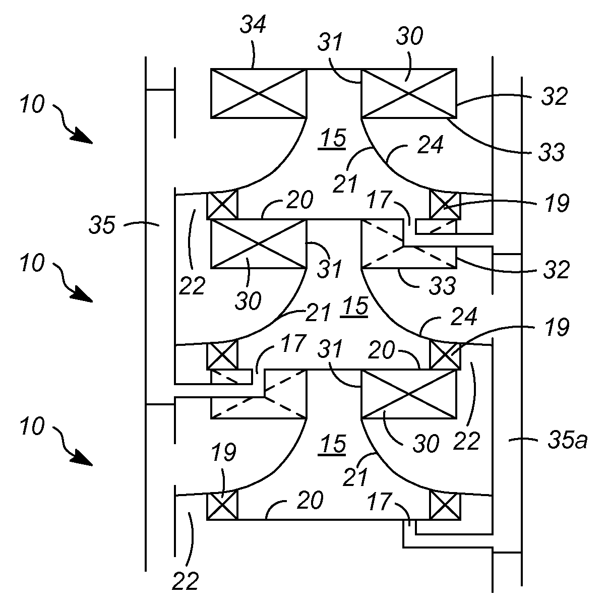
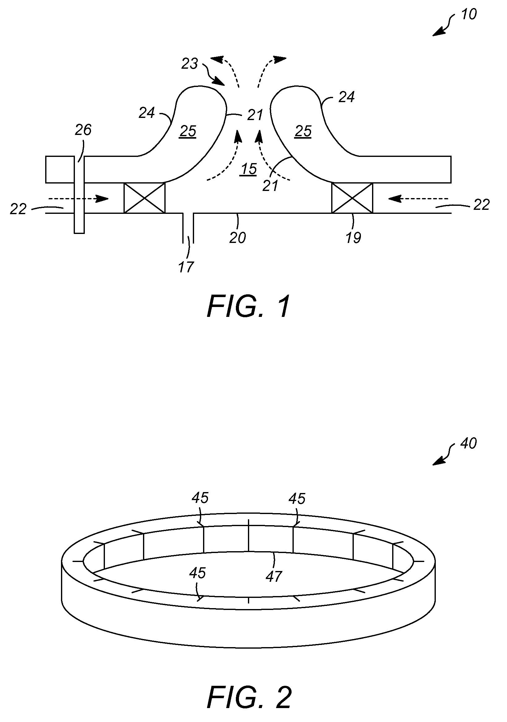
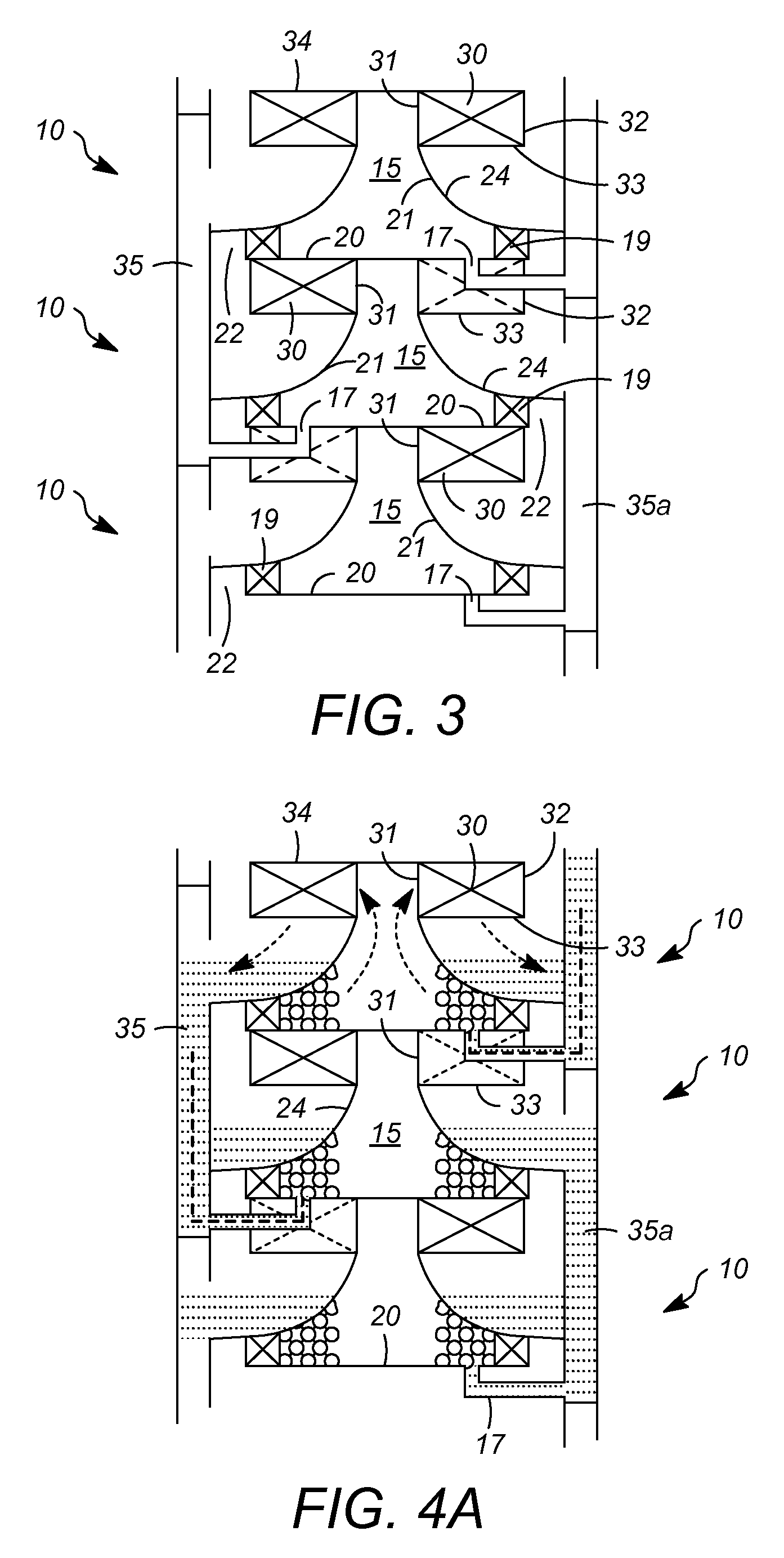
[0028]Aspects of the invention are associated with the discovery of improved vortex contacting stages having a number of advantages, as discussed above, in terms of their performance as well as their mechanical design and ease of installation and inspection / maintenance. FIG. 1 is a side view illustrating some basic features associated with a vortex contacting stage 10. In contacting zone 15, a spinning vortex of a highly dispersed vapor-liquid mixture can be produced and held in a field of centrifugal forces. In particular, the vortex is created in contacting zone 15 when vapor entering through vapor inlet 22 and then tangential flow directing device 19 rotates liquid entering through liquid inlet 17. A circular rotation of the entering vapor, with a rotational axis that substantially coincides with the axis of the cylindrical vessel, can be established using a tangential flow directing device 19, for example, having many guiding vanes and tangential slits arranged in a ring-shaped ...


PUM

PropertyMeasurementUnit
diameteraaaaaaaaaa
massaaaaaaaaaa
mass transfer rate constantaaaaaaaaaa

Abstract

Vapor-liquid contacting apparatuses, for example reactors and distillation columns (as well as reactive distillation apparatuses), comprising a vessel with one or more vortex contacting stages, are described. The one or more stages provide high interfacial area for the effective contacting of the different phases, in addition to the effective disengagement of these phases after contacting.

Description

FIELD OF THE INVENTION[0001]The invention relates to vapor-liquid contacting in reactors, fractional distillation columns, or other apparatuses which perform mass and / or heat transfer between vapor and liquid streams. The invention more specifically relates to vapor-liquid contacting apparatuses comprising one or more stages of vortex contacting.DESCRIPTION OF RELATED ART[0002]A significant objective throughout chemical and refining technologies is the improved efficiency of contacting between vapor and liquid phases. Currently, there are a wide variety of multi-phase reaction and separation processes which can benefit from an enhanced rate of vapor-liquid mass and / or heat transfer by increasing the interfacial area and turbulence between the contacting phases and thereby raising the mass transfer rate constant. These processes typically employ any of a wide range of conventional vapor-liquid contacting devices. Distillation processes for separating components based on their relativ...

Claims


Application Information

Patent Timeline
Patent Type & Authority Patents(United States)
IPC IPC(8): B01F3/04
CPCB01D3/30B01J19/006B01J10/00B01J2219/00774B01J19/24B01F23/20
Inventor TOWLER, GAVIN P.
Owner UOP LLC
Why Eureka
Try Eureka