Textured balloons

a balloon and textured technology, applied in the field of balloon catheters, can solve the problems of fragile inflatable balloons, sharp blades that can tear, cut or perforate thin balloons, and the type of bond between the blade pad and the balloon is somewhat inadequate, and achieves the effect of improving the performance of the incising devi

Active Publication Date: 2011-11-01
BOSTON SCI SCIMED INC
View PDF85 Cites 22 Cited by
  • Summary
  • Abstract
  • Description
  • Claims
  • Application Information

AI Technical Summary

Benefits of technology

[0008]In a first aspect of the present invention, a portion of the outer surface of the inflatable balloon is formed with non-smooth surface texture such as a knurling texture. A mounting pad is then adhesively bonded to the textured surface of the inflatable balloon. The textured surface provides more surface area than a similarly sized smooth surface, and accordingly, a stronger bond is obtained between the inflatable balloon and the mounting pad. Alternatively, or in addition to forming a portion of the inflatable balloon with a non-smooth surface texture, a bonding surface on the mounting pad can be formed with a non-smooth surface texture to increase the bond strength between the inflatable balloon and the mounting pad.
[0009]In another aspect of the present invention, non-bonding surfaces of the inflatable balloon (i.e. surfaces that remain exposed after the mounting pad(s) have been bonded to the inflatable balloon) are formed with a non-smooth surface texture. In one embodiment, the exposed surface of the inflatable balloon is formed with a plurality of nodules that prevent the incising elements from puncturing the inflatable balloon. In another embodiment, an exposed portion of the working section of the inflatable balloon is textured to promote traction between the inflatable balloon surface and the affected arterial wall to anchor the incising device at the treatment site during a balloon inflation. Other applications for the texture include balloon identification and the use of a spiral pattern in stripped balloons to increase flexibility with a minimal effect on burst pressure.

Problems solved by technology

In some instances, however, this type of bond between the blade pad and the balloon has been somewhat inadequate due to the inability of the adhesive to bond to the smooth surfaces of the balloon and pad.
An inadequate bond is especially troublesome in light of the grave consequences that can result if a blade pad de-bonds from the balloon while the balloon is located in a sensitive area of the patient.
In the absence of suitable precautions, the sharp blades can tear, cut or perforate the thin, fragile inflatable balloon during assembly of the cutting balloon, handling or during clinical use.
In a worst case, a balloon perforation or tear can result in an unsuccessful PTCA / PTA procedure and the loss of inflation fluid into the patient's vasculature.
If this happens, slippage can occur between the balloon and the lesion resulting in unwanted movement of the balloon relative to the lesion.
This unwanted movement is often deleterious to the PTCA and PTA procedure because dilation and cutting may not occur at the desired location in the vessel.

Method used


Image

  • Textured balloons
  • Textured balloons
  • Textured balloons

Examples


Embodiment Construction

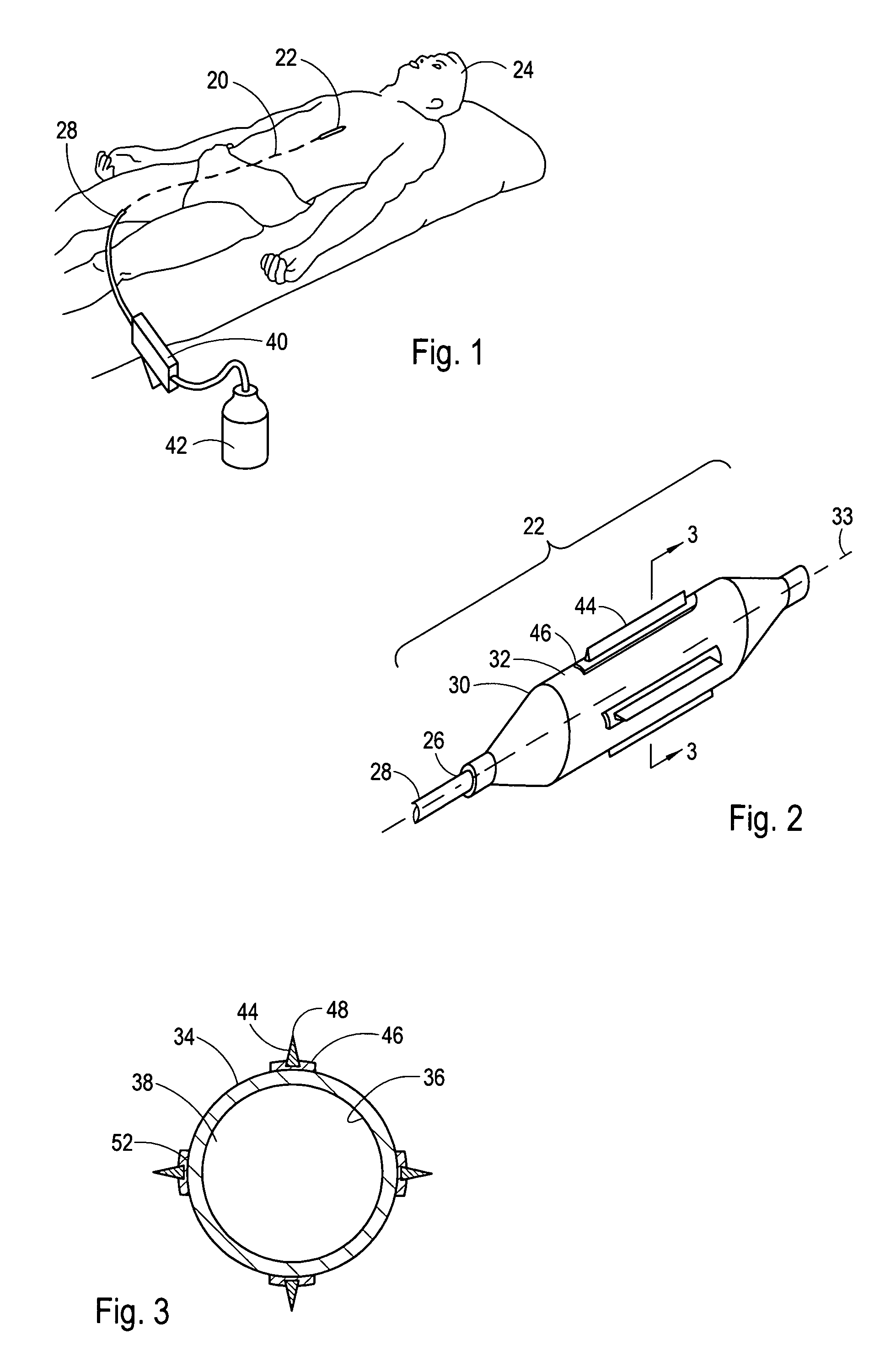
[0025]Referring initially to FIG. 1, a catheter 20 having an incising device, which in this case is a cutting balloon 22, is shown for performing a medical procedure at an internal treatment site of a patient 24. More specifically, the catheter 20 is shown positioned to treat a lesion in an upper body artery. Although the catheter 20 is capable of performing a medical procedure in an upper body artery such as a coronary artery, those skilled in the pertinent art will recognize that the use of the catheter 20 as herein described is not limited to use in a specific artery, but, instead can be used in vascular conduits and other ductal systems throughout the human body.

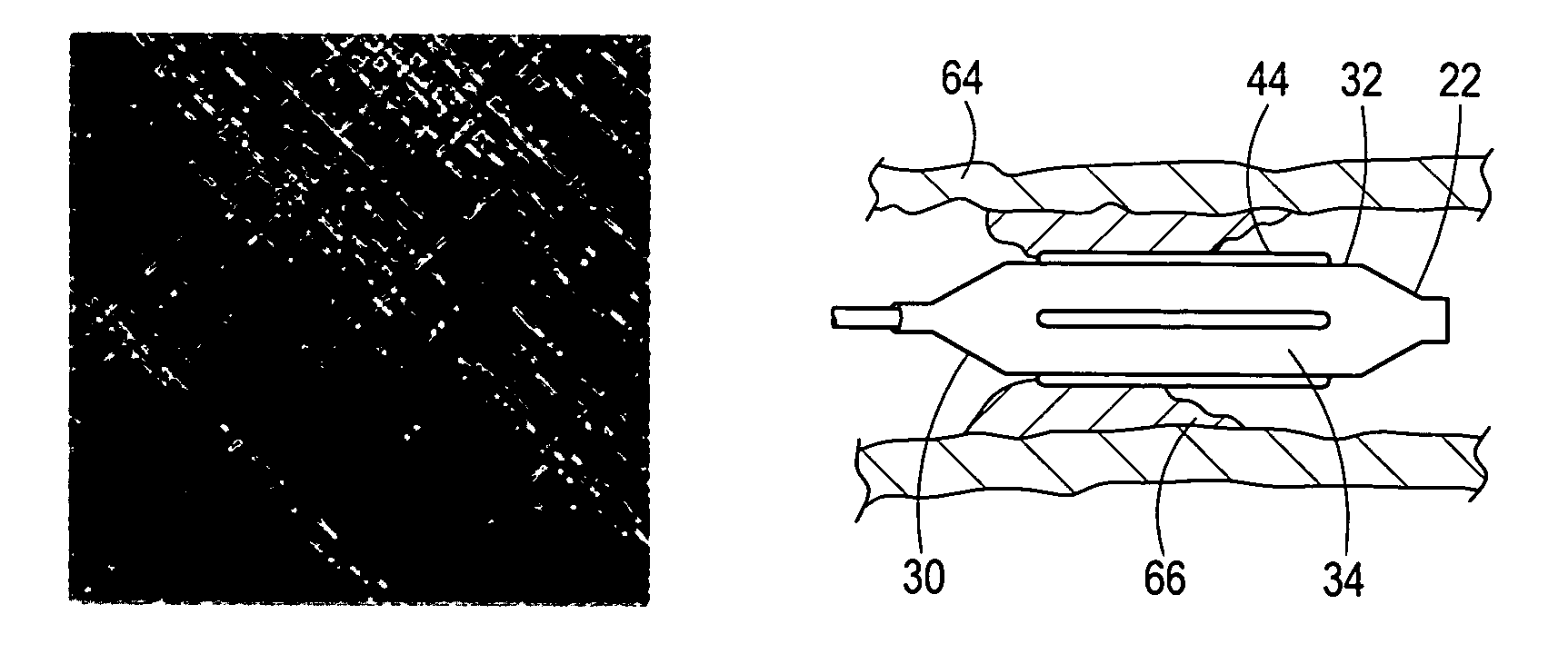
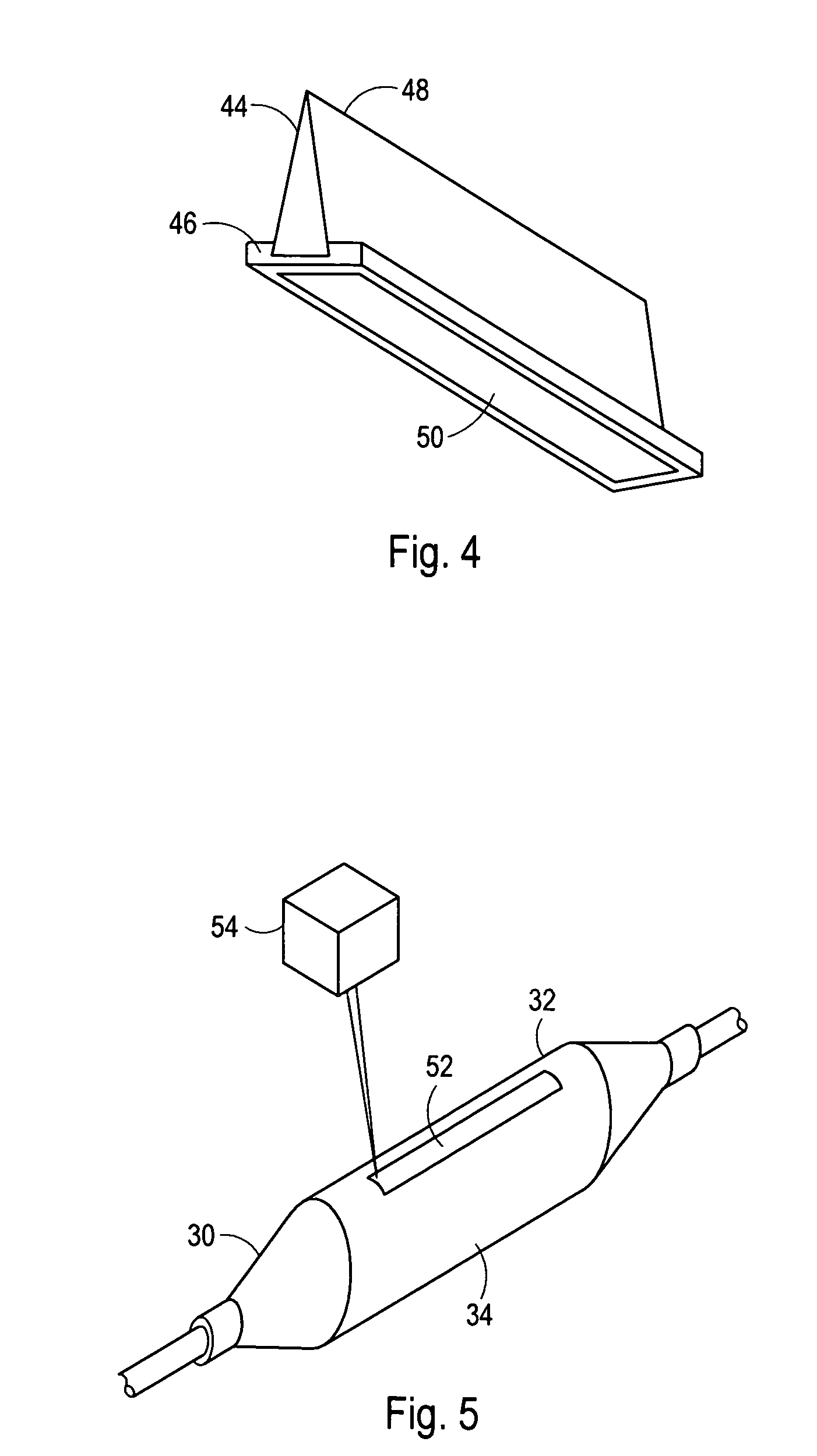
[0026]Referring now to FIG. 2, the distal portion of the catheter 20 is shown to include a cutting balloon 22 that is attached to the distal end 26 of an inflation tube 28. FIG. 2 further shows that the cutting balloon 22 can include an inflatable balloon 30 that typically includes a cylindrical shaped working section 32...


PUM


Abstract

A cutting balloon for use in PTCA and PTA procedures and methods for manufacturing cutting balloons are disclosed. One or more surfaces of the cutting balloon are formed with a non-smooth surface texture to improve adhesion between cutting blades and the inflatable balloon, to improve traction between the cutting balloon and the arterial wall, or to prevent inadvertent balloon perforation by a cutting blade. Textures, which can include a knurling texture and a nodular texture can be formed on the inflatable balloon surface directly using laser ablation. Alternatively, the texture can be formed on a mold surface used to mold the inflatable balloon from a parison. Mold surfaces can be textured using a laser photolithography process, sandblasting or a high-speed tool such as a diamond saw.

Description

FIELD OF THE INVENTION[0001]The present invention pertains generally to medical devices. More particularly, the present invention pertains to balloon catheters. The present invention is particularly, but not exclusively, useful as a cutting balloon for the revascularization of coronary and peripheral vessels.BACKGROUND OF THE INVENTION[0002]Although conventional percutaneous, transluminal, coronary angioplasty (PTCA) and percutaneous, transluminal, angioplasty (PTA) procedures have been somewhat effective in treating coronary artery disease, incising devices, such as cutting balloons, are currently viewed by many as the next generation treatment option for the revascularization of both coronary and peripheral vessels. The cutting balloon mechanism is unique in that the balloon pressure is distributed over one or more blades (i.e. microtomes). The blade(s) function as stress concentrators and cut initiators in PTCA and PTA procedures. Importantly, PTCA and PTA procedures that employ ...

Claims


Application Information

Patent Timeline
Patent Type & Authority Patents(United States)
IPC IPC(8): A61B17/22
CPCA61B17/320725A61B2017/22061A61M2025/1086
Inventor MAPES, KENNETH W.KUNIS, CHRISTOPHER G.
Owner BOSTON SCI SCIMED INC
Why Eureka
Try Eureka