Method of repairing a blisk and test pieces by welding

a technology of blisk and test piece, applied in the field of turbomachines, can solve the problems of compressor blade damage, wear or damage, difficulty in repair of rotor types, etc., and achieve the effect of great reliability

Active Publication Date: 2011-11-01
SN DETUDE & DE CONSTR DE MOTEURS DAVIATION S N E C M A
View PDF12 Cites 14 Cited by
  • Summary
  • Abstract
  • Description
  • Claims
  • Application Information

AI Technical Summary

Benefits of technology

[0020]The present invention has the advantage of allowing one-piece bladed discs to be repaired on an industrial scale by being based on the ability to control the build-up welding installations in which the heating is performed by a laser beam. Once the installation has been validated and the parameters set, all that is required is t

Problems solved by technology

However, this type of rotor has the drawback of being difficult to repair.
In operation, the compressor blades may undergo damage due to impacts caused by the ingestion, via the engine, of foreign bodies or else due to erosion caused by dust and other particles entrained by the air flowing through the engine and coming into contact with the surface of the blades.
This wear or damage, if it cannot be repaired according to the criteria specified in the manufacturer's documentation, involves replacing one or more defective blades.
In the case of one-piece bladed components, the blades are integral parts of a massive component and, unlike in conventional arrangements, they cannot be replaced or even removed in order to be repaired individually.
Repair is particularly difficult to carry out in the case of certain alloys used, the welding of which results in the formation of volume defects.
When performing build-up welding, the TIG or microplasma techniques conventionally and widely used in the aeronautical industry do not allow titanium Ti17 to be treated under conditions allowing acceptable results to be achieved.
Thes

Method used


Image

  • Method of repairing a blisk and test pieces by welding
  • Method of repairing a blisk and test pieces by welding
  • Method of repairing a blisk and test pieces by welding

Examples


Embodiment Construction

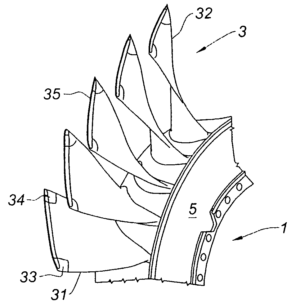
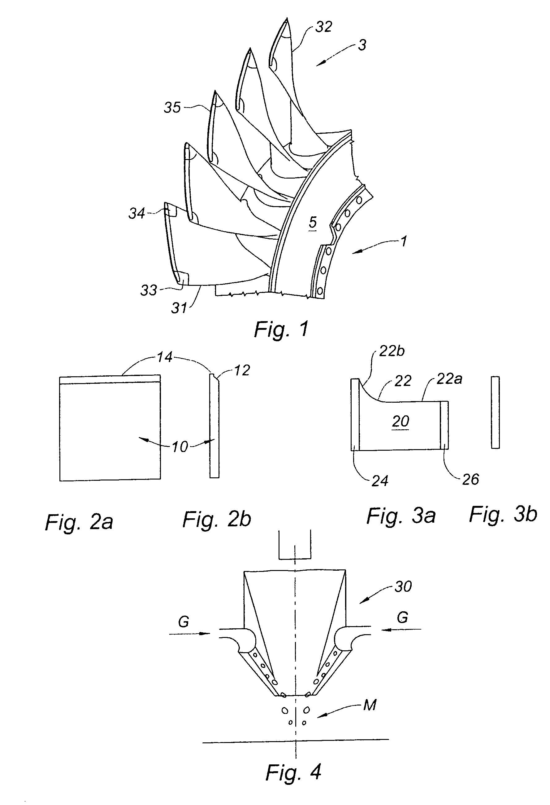
[0037]FIG. 1 shows part of a one-piece bladed disc 1. The blades 3 are radial and distributed around the periphery of a disc 5. The assembly is a one-piece assembly in the sense that it is manufactured either by machining from a single blank or by welding at least part of its components. The blades in particular are not joined to the disc by disconnectable mechanical means. The zones liable to be damaged are the leading edges 31, the trailing edges 32, the leading edge corners 33, the trailing edge corners 34 and the line of the aerofoil tip 35 provided with a thinned portion forming a sealing lip as is known.

[0038]The damage observed depends on the position of the zone. On the leading edge, IS trailing edge or aerofoil corner for example, this may be a loss of material caused by the impact of a foreign body or else a crack. At the aerofoil tip, this is more often wear due to rubbing with the engine casing. For economic and industrial reasons, it is desirable to standardize the oper...


PUM

PropertyMeasurementUnit
Speedaaaaaaaaaa

Abstract

A method of repairing a turbomachine blisk having at least one damaged zone by build-up of metal in the damaged zone using a laser build-up welding machine is disclosed. The method includes preparing the damaged zone by machining the damaged zone to obtain a zone of defined profile to be repaired, build-up welding of a start-of-run test piece that includes the defined profile using the laser build-up welding machine, checking geometric and metallurgical quality of the test piece, and build-up welding the zone to be repaired of the blisk using the laser build-up welding machine.

Description

BACKGROUND OF THE INVENTION[0001]The present invention relates to the field of turbomachines, especially aeronautical turbomachines, and is intended for the repair of moving bladed discs.[0002]To meet the increased performance requirements of engines, one-piece bladed discs or wheels, called “blisks”, are now manufactured from titanium alloy for the compressors of turbojet engines. In a conventional rotor, the blades are retained by their root, which is fitted into a housing made on the rim of the disc. The discs and blades are therefore manufactured separately before being assembled into a bladed rotor. In a blisk, the blades and the disc are machined directly from a forged blank—they form a single part. This technique permits substantial savings in the total weight of the engine to be made, but also substantial reductions in manufacturing costs. Fretting problems on the blade routes and cavities in service no longer exist.[0003]However, this type of rotor has the drawback of being...

Claims


Application Information

Patent Timeline
IPC IPC(8): B23K26/00B23P17/04B23P6/00
CPCB23P6/007F01D5/34B23K26/322B23K26/345B23K35/325B23K35/0244F01D5/005Y10T29/49318Y02T50/671Y02T50/673F05D2230/80Y10T29/49238Y10T29/49336Y10T29/49Y10T29/4932B23K26/32B23K26/342B23K2103/14Y02T50/60
Inventor BOUET, BERNARDDERRIEN, GERARDKERNEIS, STEPHANE MICHELPAGNON, CLAUDE ANDRE CHARLESPINTO, ERIC CHRISTIAN JEAN
Owner SN DETUDE & DE CONSTR DE MOTEURS DAVIATION S N E C M A
Why Eureka
Try Eureka