Circuit and method for improving the accuracy of a crystal-less oscillator having dual-frequency modes

a crystal-less oscillator and dual-frequency technology, applied in oscillator generators, pulse automatic control, instruments, etc., can solve the problems of consuming more power, requiring longer start-up times, and being more expensive than crystal-less oscillators, so as to achieve the effect of reducing power consumption

Active Publication Date: 2011-11-01
MONTEREY RES LLC
View PDF1196 Cites 32 Cited by
  • Summary
  • Abstract
  • Description
  • Claims
  • Application Information

AI Technical Summary

Benefits of technology

[0011]According to one embodiment, a clock generation circuit is provided for improving the accuracy of a low power oscillator circuit contained therein. In general, the clock generation circuit may include a crystal-less oscillator having at least two distinct frequency modes, including a low frequency mode and a high frequency mode. In some cases, the crystal-less oscillator may be adapted to generate a first clock frequency with relatively high accuracy and a second clock frequency with relatively low accuracy. A calibration and control circuit is included within the clock generation circuit for increasing the accuracy of the second clock frequency. As described in more detail below, the calibration and control circuit may increase accuracy by using the first clock frequency to calibrate the second clock frequency, which is generated by the same crystal-less oscillator. In one implementation, the first clock frequency may be significantly lower than the second clock frequency. Examples of crystal-less oscillators adapted to provide highly accurate, low frequency signals and less accurate, high frequency signals include, but are not limited to, relaxation oscillators and ring oscillators.
[0012]In some implementations, the calibration and control circuit may include a frequency multiplier, a pair of counters and control logic. The frequency multiplier may be coupled to the crystal-less oscillator for generating a frequency multiplied version of the first clock signal. For example, the frequency multiplier may be enabled for a short period of time to generate a third clock frequency by multiplying the first clock frequency by an amount, which enables the third clock frequency to be relatively close to the second clock frequency. In some cases, a PLL may be used to provide accurate frequency multiplication. During low frequency modes, the PLL may be disabled to reduce power consumption in the clock generation circuit. The first clock frequency generated by the crystal-less oscillator may be used for clocking downstream components during this time.
[0013]The PLL may be enabled for a short period of time during high frequency modes to generate the third clock frequency, as mentioned above. More specifically, the PLL may be run in a closed loop mode until the third clock frequency is generated from the first clock frequency. The PLL may then be run in an open loop mode to maintain the third clock frequency while: (i) the crystal-less oscillator is switched from the first clock frequency to the second clock frequency, and (ii) a frequency difference between the third clock frequency and the second clock frequency is determined. After the frequency difference is determined the PLL may be disabled to reduce power consumption in the clock generation circuit.
[0019]In addition, the system may include one or more components, which are coupled to the clock generation circuit for receiving the first clock signal and / or the calibrated second clock signal. In one implementation, at least one of the system components may be a dual-mode component, which is adapted to use either the first clock signal or the calibrated second clock signal, depending on a current mode of operation. In one example, the dual-mode component may be a microcontroller or microprocessor, which is adapted to minimize power consumption by using the calibrated second clock signal during awake modes and the first clock signal during sleep modes. In other implementations, at least one of the system components may include digital logic, which is adapted to use the calibrated second clock signal periodically or while performing certain functions. In one example, the digital logic component may be a receiver, transmitter or transceiver, which is adapted to use the calibrated second clock signal while receiving or transmitting data.

Problems solved by technology

Although crystal oscillators are used in many high-precision applications (e.g., watches, clocks, radio transmitters and receivers, and communication devices such as Local Area Network (LAN) interfaces), they are generally more costly, consume larger amounts of power and require longer start-up times than crystal-less oscillators.
Therefore, crystal oscillators may not be desired in all applications.
Crystal-less oscillators are generally less accurate than crystal oscillators and other oscillators built with other external components, such as Surface Acoustic Wave (SAW) devices and ceramic resonators.
However, since the method requires at least one crystal oscillator for calibration purposes, it cannot be used to provide a low cost and / or low power solution to the problem.
The external crystal also consumes space on the circuit board and increases the pin count on the IC package (e.g., two extra pins may be needed to connect the external crystal to the package).

Method used


Image

  • Circuit and method for improving the accuracy of a crystal-less oscillator having dual-frequency modes
  • Circuit and method for improving the accuracy of a crystal-less oscillator having dual-frequency modes
  • Circuit and method for improving the accuracy of a crystal-less oscillator having dual-frequency modes

Examples


Embodiment Construction

[0029]Oscillator circuits are included within many electronic devices (e.g., computer systems, cellular phones, and palmtop computing devices) to generate a clock signal for synchronizing, pacing and coordinating the operations of various components (e.g., microcontrollers, microprocessors, and communication interfaces) within the electronic device. Two main concerns among users and manufacturers of electronic devices, particularly portable electronic devices, is the ability to reduce the size and cost of the electronic device. Additional concerns include pin usage and start-up time. As described in more detail below, some electronic devices attempt to address these concerns by using crystal-less oscillator circuits at least some of the time. These oscillators are usually less accurate than their high precision counterparts. Therefore, a need exists for an improved circuit and method for improving the accuracy of a crystal-less oscillator circuit.

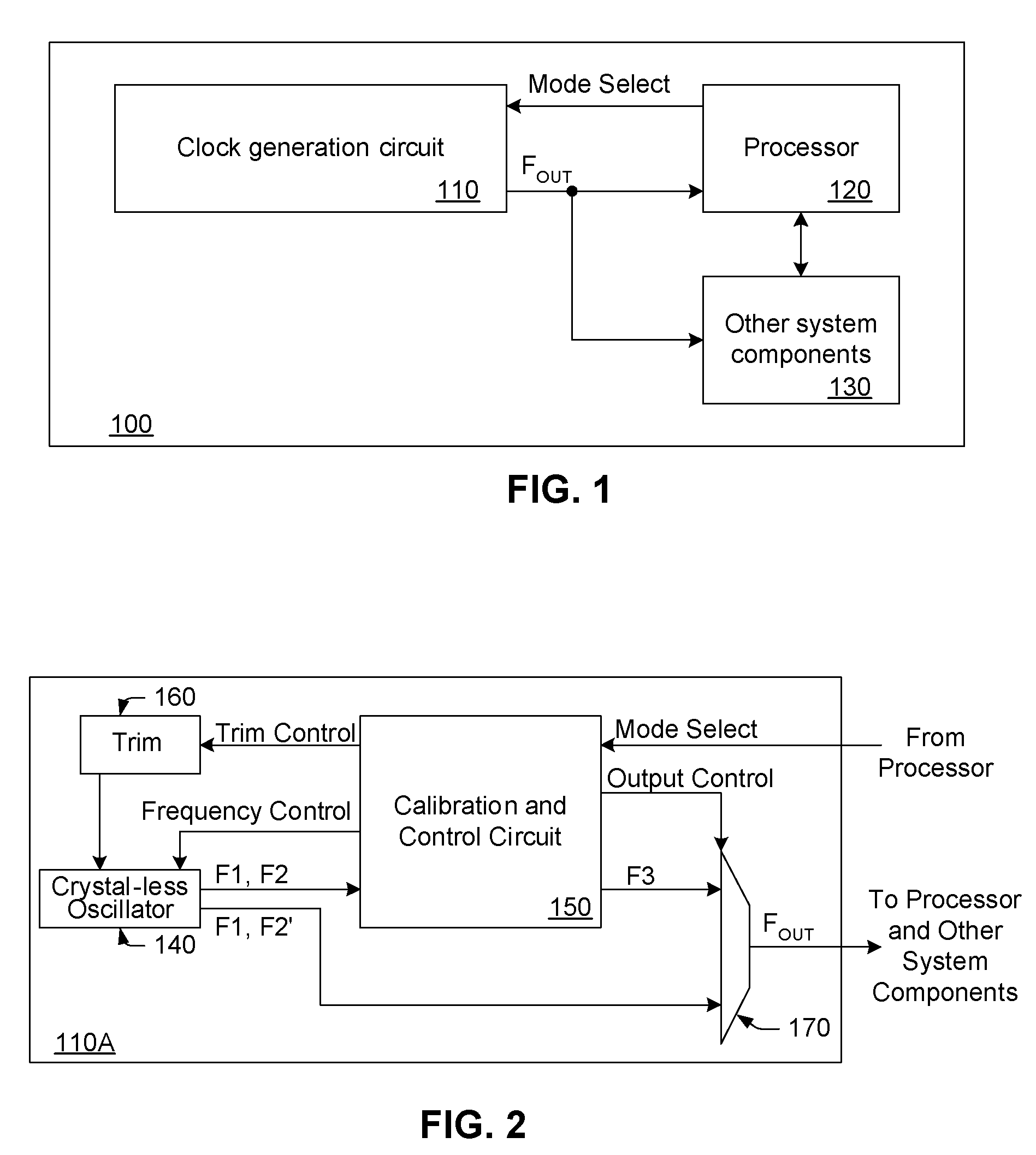
[0030]FIG. 1 illustrates a general e...


PUM


Abstract

A clock generation circuit is provided for improving the accuracy of a low power oscillator circuit contained therein. The clock generation circuit includes a crystal-less oscillator having at least two distinct frequency modes, including a low frequency mode and a high frequency mode. In some cases, the crystal-less oscillator may be adapted to generate a first clock frequency with relatively high accuracy and a second clock frequency with relatively low accuracy. A calibration and control circuit is included within the clock generation circuit for increasing the accuracy of the second clock frequency. In particular, the calibration and control circuit increases accuracy by using the first clock frequency to calibrate the second clock frequency generated by the same crystal-less oscillator. A system comprising the clock generation circuit and methods for operating a crystal-less oscillator having at least two distinct frequency modes are also provided herein.

Description

BACKGROUND OF THE INVENTION[0001]1. Field of the Invention[0002]This invention relates to clock signal generation and, more particularly, to an improved clock generation circuit and method for operating a crystal-less oscillator having at least two distinct frequency modes.[0003]2. Description of the Related Art[0004]The following descriptions and examples are given as background only.[0005]Many integrated circuits (ICs) feature on-chip oscillators. For example, many processor-based systems have internal oscillators, which enable the processor (e.g., a CPU or MCU) to generate its own clock signal without the need for an external oscillator. In some cases, the processor may be configured to operate at two different clock frequencies. In one example, the processor may use a high frequency clock during “awake” modes and a low frequency clock during “sleep” modes. In another, the processor may operate at more than one frequency while awake to trade off speed and power consumption.[0006]...

Claims


Application Information

Patent Timeline
Patent Type & Authority Patents(United States)
IPC IPC(8): H03L7/06
CPCH03L7/104
Inventor WRIGHT, DAVID G.WILLIAMS, TIMOTHY J.
Owner MONTEREY RES LLC
Why Eureka
Try Eureka