Mass flow controller

a flow controller and controller technology, applied in the direction of valve operating means/release devices, process and machine control, instruments, etc., can solve the problems of not being able to achieve adequate flow rate control, excessive flow rate response to change, and changes beyond the prescribed level, so as to achieve the effect of sacrificing the speed of following

Active Publication Date: 2011-11-15
HORIBA STEC CO LTD
View PDF16 Cites 6 Cited by
  • Summary
  • Abstract
  • Description
  • Claims
  • Application Information

AI Technical Summary

Benefits of technology

[0010]An aspect of the present invention provides a mass flow controller that can substantially prevent a flow rate change from occurring due to a pressure change without a substantial sacrifice in the speed of following the change of the flow rate setting value. The mass flow controller can be used in a system in which crosstalk can occur.
[0012]The mass flow controller thus configured switches the control between the stable period and the changing period. Therefore, in the changing period in which the flow rate setting value changes, the actual flow rate can be made to follow the changed flow rate setting value substantially quickly. In the stable period in which the flow rate setting value does not change significantly, the flow rate can be substantially prevented from excessively responding to any disturbance, such as a pressure change that occurs on the primary side (a pressure change that occurs on the upstream side of the mass flow controller), thereby stabilizing the actual flow rate.
[0019]Since the control is switched between the stable period and the changing period, the mass flow controller can suppress a flow rate change without sacrificing the speed of following the change of the flow rate setting value even if a disturbance, such as a pressure change, occurs and can be used in a system in which a crosstalk may occur.

Problems solved by technology

As a result the related art control method, which is based on the assumption that the pressure regulator controls the pressure change, may not be able to achieve adequate flow rate control.
More specifically, if the related art control method disclosed in the Patent Document 1 is used, and if the pressure on the primary side (the pressure on the upstream side of the mass flow controller) changes beyond a certain level, the flow rate excessively responds to the change and changes beyond a prescribed level.

Method used


Image

  • Mass flow controller
  • Mass flow controller
  • Mass flow controller

Examples


Embodiment Construction

[0026]In the following, an exemplary, non-limiting embodiment of the present invention will be described with reference to the drawings.

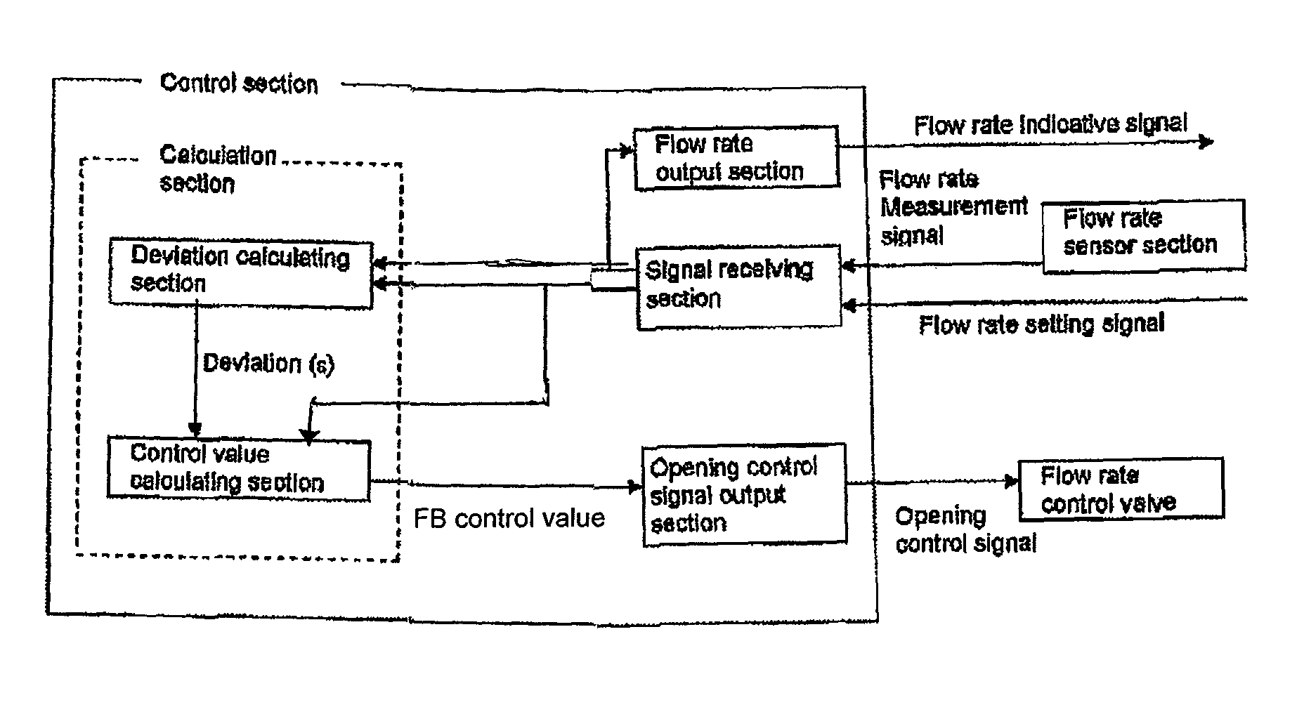
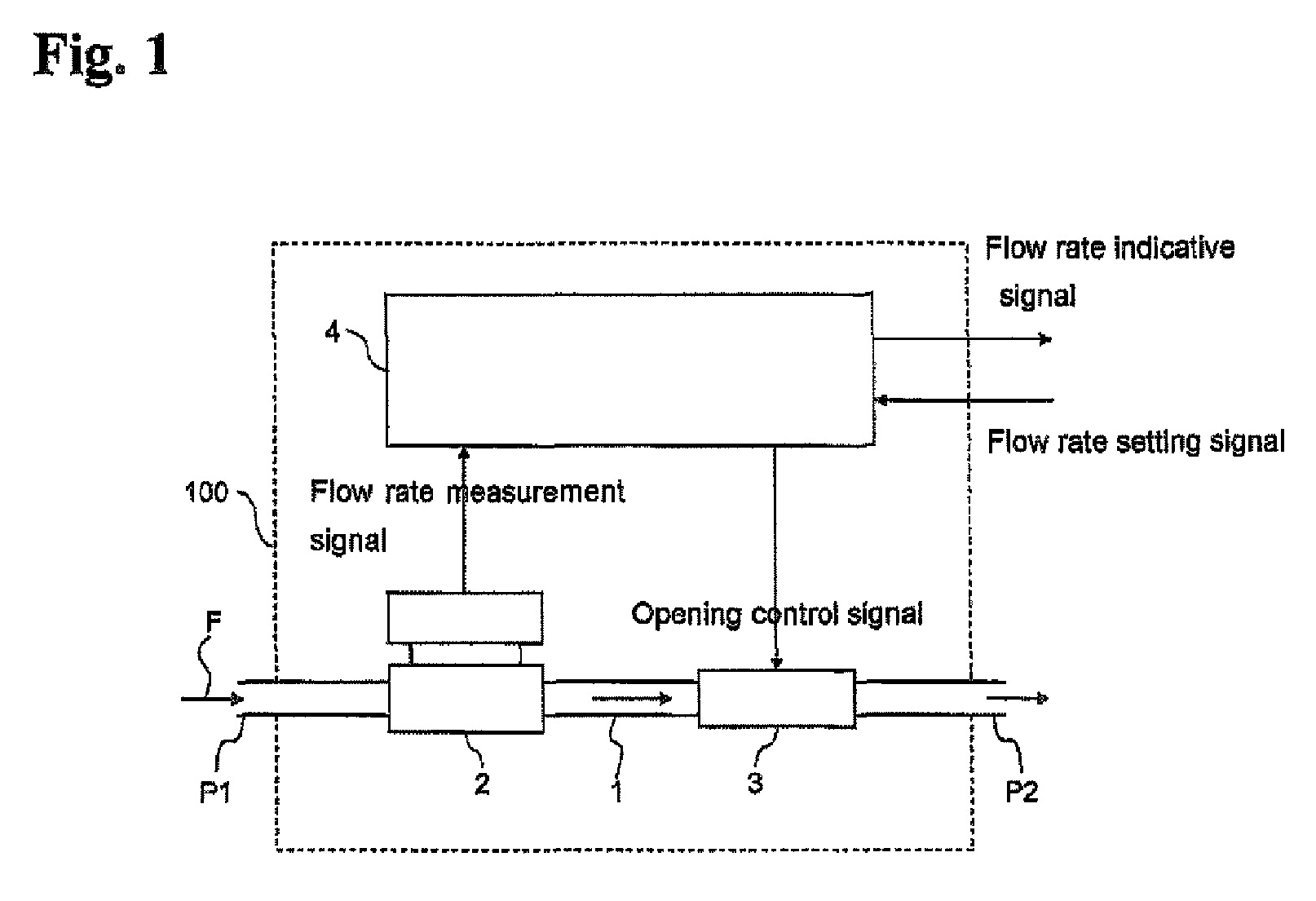
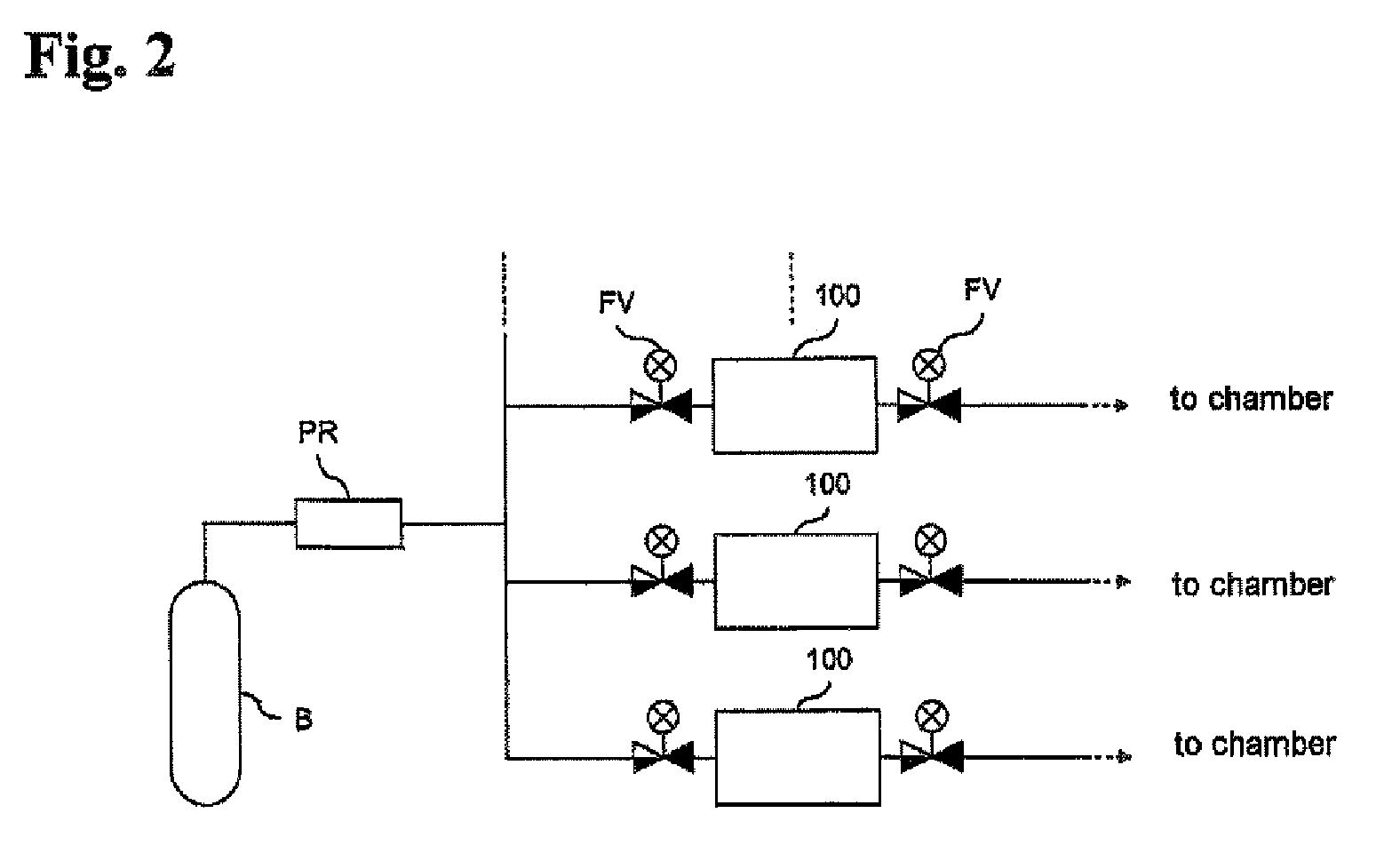
[0027]As shown in the schematic diagram of FIG. 1, a mass flow controller 100 according to the exemplary embodiment comprises an internal channel 1, a flow rate sensor section 2 that measures the flow rate of a fluid F flowing through the internal channel 1, a flow rate control valve 3 disposed downstream of the flow rate sensor section 2, and a control section 4. The mass flow controller 100 may be used in a gas supply system that supplies gas to a chamber in a semiconductor process as shown in FIG. 2.

[0028]The internal channel 1 has an inlet port P1 on the upstream side and an outlet port P2 on the downstream side. For example, the inlet port P1 may be connected to a fluid supply source B, such as a cylinder, via an external pipe, and the outlet port 2 is connected to a chamber for semiconductor manufacture (not shown) via an external pipe. In thi...


PUM


Abstract

A mass flow controller has: a flow rate sensor section that measures the flow rate of a fluid and outputs a flow rate measurement signal indicating the measurement value; a flow rate control valve disposed upstream or downstream of the flow rate sensor section; a calculation section that calculates a feedback control value to be supplied to the flow rate control valve by performing at least a proportional calculation on the deviation of the flow rate measurement value indicated by the flow rate measurement signal from a flow rate setting value; and an opening control signal output section that generates an opening control signal based on the feedback control value and outputs the opening control signal to the flow rate control valve. The function used for calculating the gain value in the proportional calculation differs between a changing period and a stable period.

Description

BACKGROUND OF THE INVENTION[0001]1. Technical Field[0002]Aspects of the present invention relate to a mass flow controller that controls the flow rate of a fluid, such as gas and liquid.[0003]2. Related Art[0004]In a related art semiconductor manufacturing apparatus to which various kinds of gas used for manufacturing a semiconductor are supplied, a mass flow controller is provided for each gas supply channel to adjust the flow rate of the gas. A related art pressure regulator is connected in series to each mass flow controller so as to prevent an extreme change in pressure in the channel to which the mass flow controller is attached, thereby facilitating flow rate control.[0005]A related art flow rate control method for the mass flow controller is PID (proportional integral derivative) control. For example, a related art feedback control is based on a variation of the related art PID control disclosed in Japanese Laid-Open Patent Application No. 2004-280689 (hereafter “Patent Docum...

Claims


Application Information

Patent Timeline
Patent Type & Authority Patents(United States)
IPC IPC(8): F16K31/02
CPCG05D7/0635Y10T137/2703Y10T137/7759Y10T137/7761
Inventor TAKAHASHI, AKITOYONEDA, YUTAKA
Owner HORIBA STEC CO LTD
Why Eureka
Try Eureka